
Improved mold temperature controller

A mold temperature controller and mold technology, applied in the field of mechanical processing equipment, can solve problems such as clogging pipes or related equipment, shortening the service life of molds, and affecting product quality, so as to achieve the effects of ensuring normal use, prolonging service life, and ensuring quality

Inactive Publication Date: 2017-05-24
TIANJIN AODENA TECH
View PDF1 Cites 0 Cited by
  • Summary
  • Abstract
  • Description
  • Claims
  • Application Information

AI Technical Summary

Problems solved by technology

Most of the existing mold temperature controllers use water to cool the mold and other operations. Most of the connections between the mold and the mold temperature controller are connected by pipes and other related equipment. Although a filter is generally installed at the water inlet end, the water in the pipes and other related equipment When flowing, it is very easy to be polluted by impurities left in the pipeline or related equipment. If the polluted water flows into the mold, it will easily pollute the mold and shorten the service life of the mold. For direct immersion of the finished product in the mold In the case of cooling in water, the finished product in the mold is also very susceptible to water pollution, which may affect the relevant appearance of the product or its physical or chemical properties, thereby affecting the quality of the product and bringing unnecessary costs to the enterprise. At the same time, the water flowing out of the mold after cooling may also be mixed with impurities in the mold, and then remain in the pipeline or related equipment, which will block the pipeline or related equipment and affect the use
[0003] In addition, the pipes connected to the existing mold temperature controllers are mostly airtight connections. If the pressure in the pipes is too high and not detected in time, it is very likely to cause serious production safety accidents, such as explosions, etc.

Method used


Image

  • Improved mold temperature controller

Examples


Embodiment Construction

[0020] In order to further understand the content, characteristics and effects of the present invention, the following examples are given, and detailed descriptions are given below with reference to the accompanying drawings. It should be noted that this embodiment is descriptive, not restrictive, and cannot thereby limit the protection scope of the present invention.

[0021] The structural connections and working principles not specifically described in this patent application can be understood as prior art, such as the content disclosed in the patent publication CN204431572U.

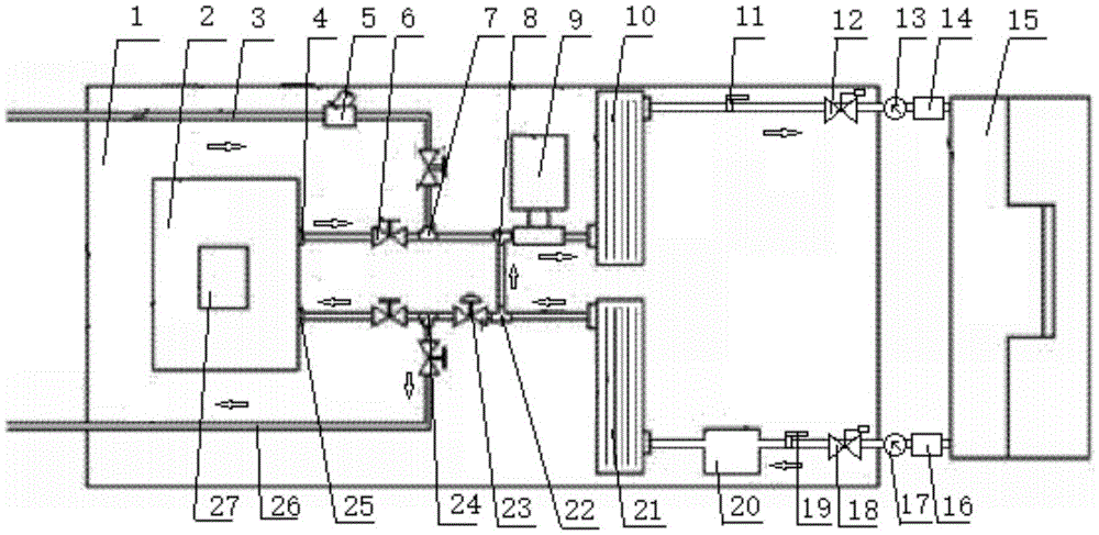
[0022] An improved mold temperature machine, such as figure 1 As shown, the mold temperature machine includes a box body 1, a water storage tank 2 arranged on the box body, a plurality of pipes arranged in the box body, a pump 9 arranged under the box body, and a No. 1 heating tank arranged in the box body. Device 10 and No. 2 heating device 21, the water storage tank is provided with a water outlet...


PUM


Abstract

The invention relates to an improved mold temperature controller. The improved mold temperature controller comprises a box body, a water storage tank, a plurality of pipelines, a pump, a first heating device and a second heating deice, wherein the water storage tank is installed on the box body, the pipelines are installed in the box body, the pump is installed below the box body, and the first heating device and the second heating device are installed in the box body. A water outlet and a water inlet are formed in the water storage tank; a first filter is installed on the portion, between the water output end of the first heating device and the water input end of a mold and near the water input end of the mold, of the pipeline; and a second filter is installed on the portion, between the output end of the mold and the water input end of the second heating device and near the output end of the mold, of the pipeline. According to the improved mold temperature controller, by installing the first filter, normal use of the mold is ensured, the service life of the mold is prolonged, the quality of products is guaranteed, and economical benefits of an enterprise are improved; and by installing the second filter, normal use of the pipelines and related equipment is guaranteed, and production efficiency is improved.

Description

technical field [0001] The invention belongs to the technical field of mechanical processing equipment, in particular to an improved mold temperature controller. Background technique [0002] Mold temperature controller is a kind of mold temperature control machine. With the development of machinery industry, mold temperature controller is more and more widely used. Now the temperature controlled by mold temperature controller can reach plus or minus 0.1℃. Most of the existing mold temperature controllers use water to cool the mold and other operations. Most of the connections between the mold and the mold temperature controller are connected by pipes and other related equipment. Although a filter is generally installed at the water inlet end, the water in the pipes and other related equipment When flowing, it is very easy to be polluted by impurities left in the pipeline or related equipment. If the polluted water flows into the mold, it will easily pollute the mold and sho...

Claims


Application Information

Patent Timeline
Patent Type & Authority Applications(China)
IPC IPC(8): B29C33/04
CPCB29C33/04
Inventor 滑鹏高
Owner TIANJIN AODENA TECH
Learn More