Round bale baler motor shaft welding tool

A technology of motorized shafts and round bales, which is applied in welding equipment, manufacturing tools, auxiliary devices, etc., can solve the problems that the quality of the moving shaft cannot be guaranteed, the welding accuracy of the moving shaft is low, and the labor intensity is high, so as to improve the Quality and interchangeability, simple structure, and the effect of reducing labor intensity

Active Publication Date: 2018-03-30
LINYING COUNTY YING MACHINERY MFG
View PDF5 Cites 0 Cited by
  • Summary
  • Abstract
  • Description
  • Claims
  • Application Information

AI Technical Summary

Problems solved by technology

[0002] The moving shaft of the round bale baler is the key component of the round bale baler. The angle requirements between the oil top nose of the moving shaft and the flange and the deflection fixing hole of the moving shaft tube are relatively strict. At present, the round bale pressing Most of the welding and manufacturing of the tying motor shaft adopts manual positioning, the whole work is labor intensive and the production efficiency is low
In addition, since the entire welding process is done manually, and human eyes have visual errors, resulting in a low level of welding accuracy of the moving shaft, so that the quality of the moving shaft cannot be guaranteed, and the interchangeability of the moving shaft is poor.

Method used


Image

  • Round bale baler motor shaft welding tool
  • Round bale baler motor shaft welding tool
  • Round bale baler motor shaft welding tool

Examples


Embodiment Construction

[0016] The present invention will be further explained below in conjunction with the drawings.

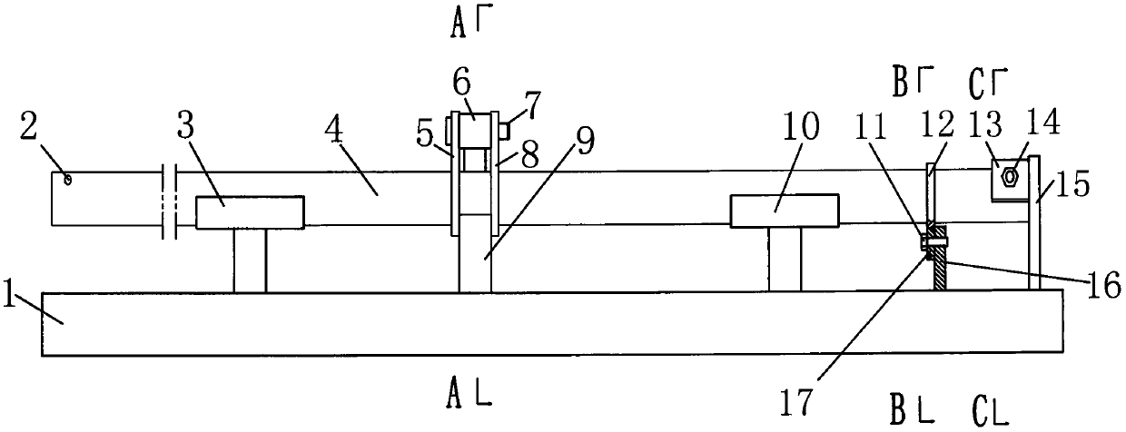
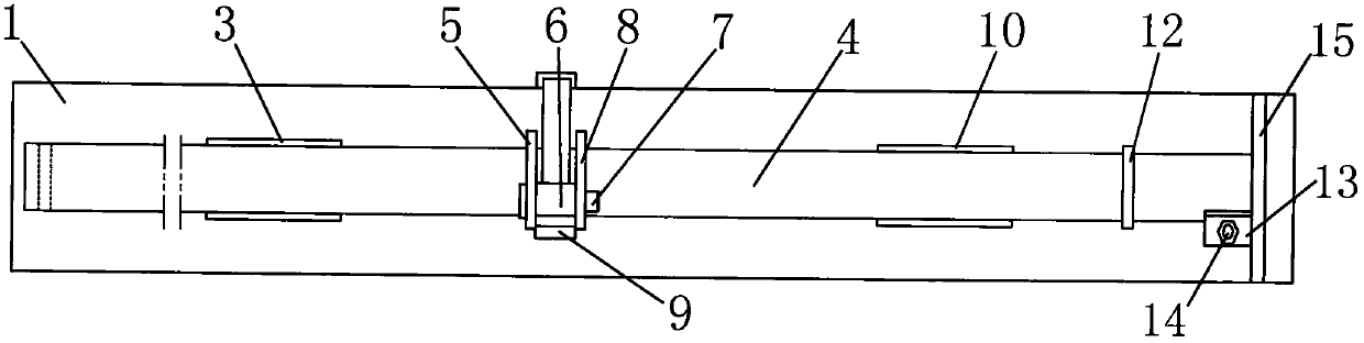
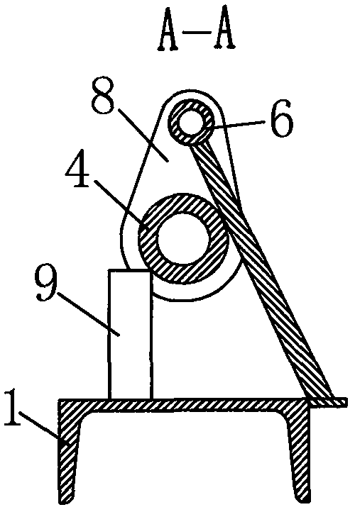
[0017] Such as Figure 1-Figure 7 As shown, the motorized shaft welding tool for round bale pressing includes a bottom plate 1, on which a first bracket 3, a second bracket 10, a flange positioning plate 16, and a moving shaft tube end positioning plate 15 are fixed. ; The flange positioning plate 16 is provided with a flange lower hole positioning block 17; the moving shaft tube end positioning plate 15 is fixed with a moving shaft tube deflection fixing hole positioning plate 13, and the moving shaft tube deflection fixing hole positioning plate A positioning pin 14 is provided for the pivoting fixed hole of the moving shaft tube; the middle position of the bottom plate 1 is fixed with the oil top nostril positioning sleeve 6, the oil top nose front width positioning plate 9, the oil top nostril positioning sleeve 6, the oil top nose front width positioning The board 9 is up and do...


PUM


Abstract

The invention discloses a welding tool for a movable shaft of a round straw bale baling machine. The welding tool comprises a base plate. An oil jack nose hole positioning sleeve and a wide oil jack nose front positioning plate are fixedly connected to the middle of the base plate. One end of the movable shaft is connected with a movable shaft pipe end positioning plate in an abutting mode. A movable shaft pipe deflection fixing hole positioning pin is inserted into a movable shaft pipe deflection fixing hole. The middle of the movable shaft is sleeved with a first oil jack nose and a second oil jack nose. An oil jack nose hole positioning pin penetrates through oil jack nose holes in the upper ends of the first oil jack nose and the second oil jack nose and the oil jack nose hole positioning sleeve. A movable shaft pipe is arranged in an upper hole of a flange in a sleeved mode, and a flange lower hole positioning block is mounted in a lower hole of the flange in a sleeved mode. The flange, the first oil jack nose and the second oil jack nose are welded to the movable shaft. According to the welding tool for the movable shaft of the round straw bale baling machine, the angles between the oil jack noses of the movable shaft and the flange as well as between the oil jack noses and the move shaft pipe deflection fixing hole are accurately positioned, labor intensity is greatly relieved, and production efficiency is greatly improved; and meanwhile, the quality and interchangeability of the movable shaft of the round straw bale baling machine are improved.

Description

Technical field [0001] The invention relates to the field of manufacturing equipment for a round bale pressing machine, in particular to a round bale pressing motor shaft welding tool. Background technique [0002] The moving shaft of the round bale baler is a key component of the round bale baler. The angle between the oil nose of the moving shaft and the flange and the fixed hole of the moving shaft tube is strict. The current round bale pressure Most of the welding manufacturing of the bundled motor shaft adopts manual positioning, the whole work is labor-intensive and the production efficiency is low. In addition, since the entire welding process is done manually, and human eyes have visual errors, the welding accuracy of the moving shaft is low, so that the quality of the moving shaft cannot be guaranteed, and the interchangeability of the moving shaft is poor. Summary of the invention [0003] The purpose of the present invention is to provide a motorized shaft welding tool...

Claims


Application Information

Patent Timeline
Patent Type & Authority Patents(China)
IPC IPC(8): B23K37/04
CPCB23K37/0443
Inventor 张义张志刚李冠峰祁学民刘存祥王万章赵明邰富刚孙天龙陈坡祁飞淼田璐张中甫罗义刘清江李长法陈俊生李洪涛
Owner LINYING COUNTY YING MACHINERY MFG
Why Eureka
Try Eureka