
A belling machine

A technology of belling machines and racks, applied in the field of belling machines, can solve the problems of poor precision of belling machines, low qualified rate of finished products, resource consumption, etc., and achieve the effects of improving production efficiency, avoiding inaccurate positioning, and reliable structure

Active Publication Date: 2019-05-21
广东杰鑫品科技有限公司
View PDF8 Cites 0 Cited by
  • Summary
  • Abstract
  • Description
  • Claims
  • Application Information

AI Technical Summary

Problems solved by technology

[0003] The technical problem to be solved by the present invention is: the existing belling machine has poor precision, low qualified rate of finished products, often needs rework, and consumes resources

Method used

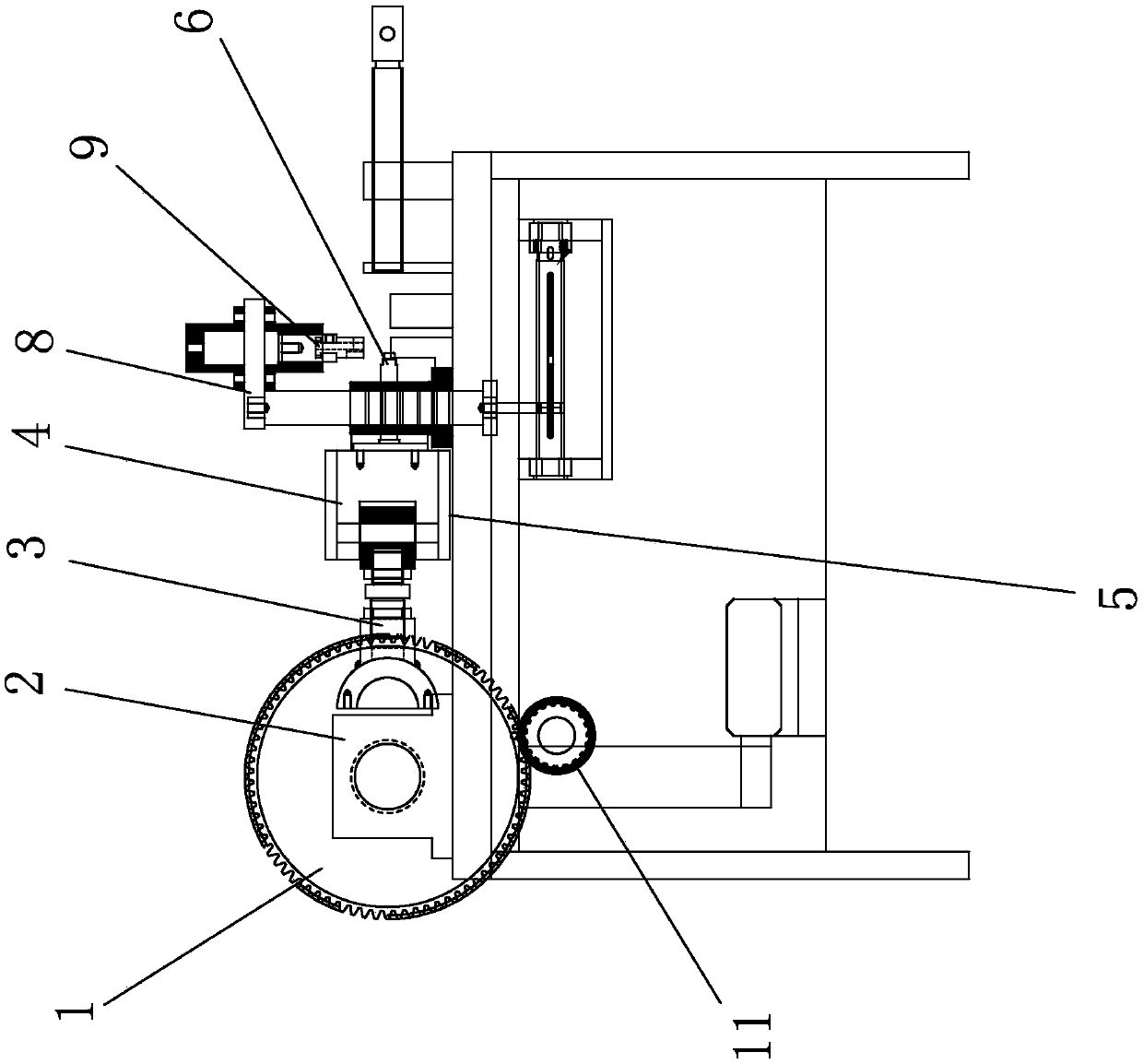

Image

  • A belling machine
  • A belling machine
  • A belling machine

Examples


Embodiment Construction

[0016] The idea, specific structure and technical effects of the present invention will be clearly and completely described below in conjunction with the embodiments and accompanying drawings, so as to fully understand the purpose, features and effects of the present invention. Apparently, the described embodiments are only some of the embodiments of the present invention, rather than all of them. Based on the embodiments of the present invention, other embodiments obtained by those skilled in the art without creative efforts belong to The protection scope of the present invention. In addition, all the connection / connection relationships mentioned in this article do not refer to the direct connection of components, but mean that a better connection structure can be formed by adding or reducing connection accessories according to specific implementation conditions. The various technical features in the invention can be combined interactively on the premise of not conflicting wi...


PUM


Abstract

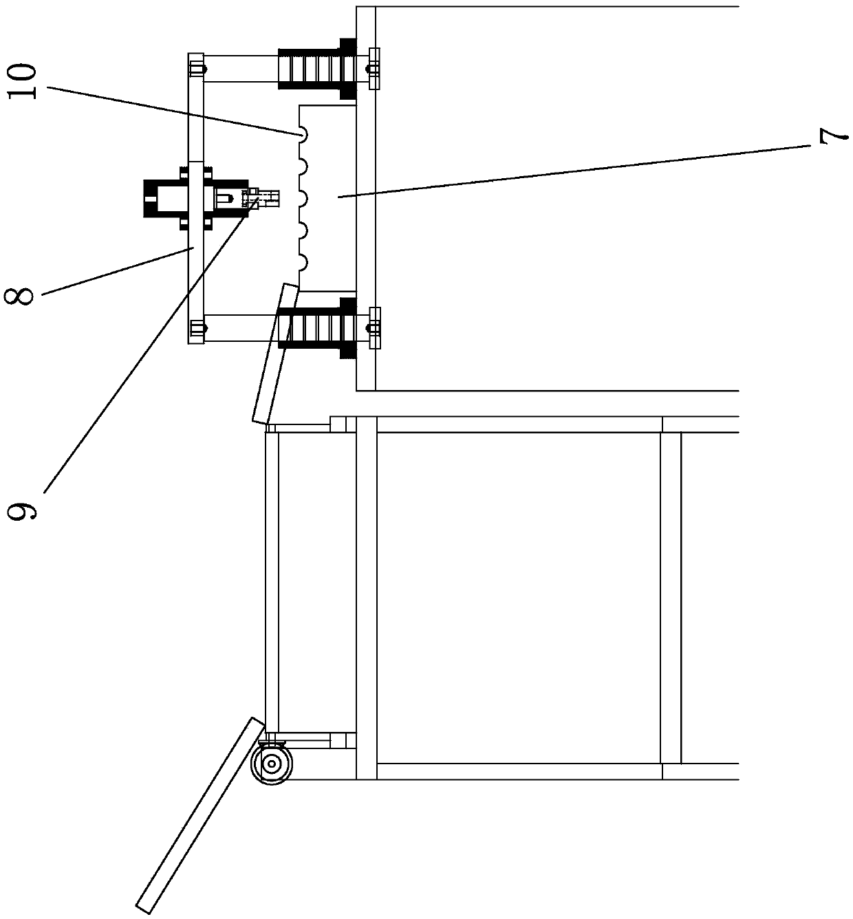
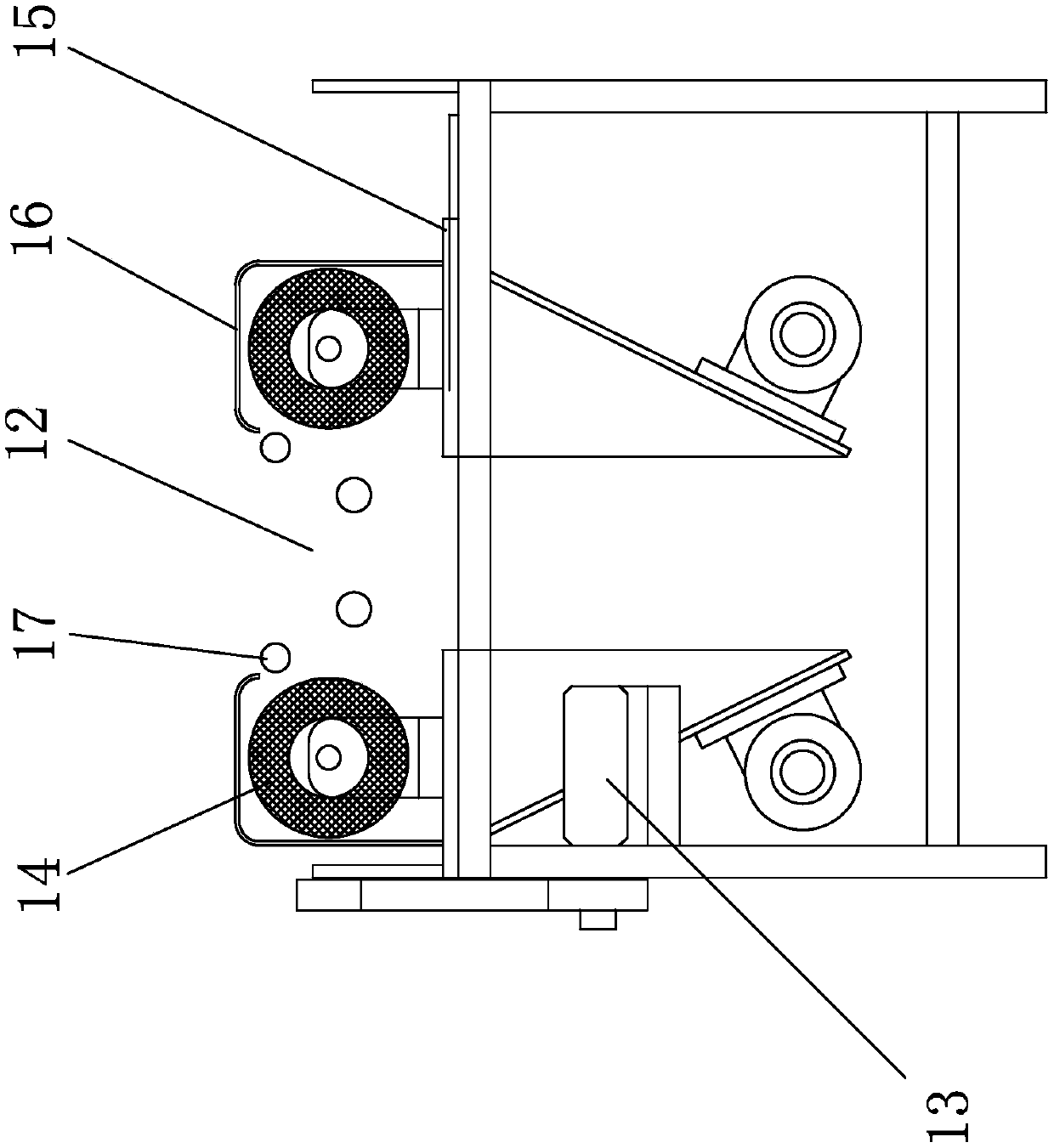
The invention discloses a pipe expanding machine. The pipe expanding machine comprises a rack, wherein the rack comprises a pipe supply mechanism, a pipe positioning mechanism, a pipe expanding mechanism and a pipe discharge hole; the pipe expanding mechanism comprises a first motor, a first transmission gear, a crankshaft, a connecting rod, a slide base, a guide rail and a punch; the pipe positioning mechanism comprises a discharge rack, a second motor, a feeding device, a lifting platform and a pressing part. The pipe expanding machine is conveyed to provide power for the punch by virtue of mechanical transmission, so that circulating reciprocating of the punch can be realized by only needing to provide one-way power output, and therefore, the pipe expanding machine is reliable, simple and durable in structure; the discharge frame is additionally arranged, so that pipes can keep proper spacing before entering an expanding station, and the pipes on the discharge frame are synchronously stepped forwards though a cross rod, so that inaccurate positioning is effectively avoided. The pipe expanding machine can be used for improving production efficiency of the pipe expanding machine, and reduces manpower resource cost.

Description

technical field [0001] The invention relates to the technical field of stamping machines, in particular to a flaring machine. Background technique [0002] The connecting pipelines inside the air conditioner are relatively complicated, and the interfaces of some pipelines need to be flared to be smoothly connected with other components. There are many flaring machines on the market for making such flaring pipe fittings, but for the convenience of assembly, the whole purchased air cylinder or hydraulic cylinder is mainly used as the power source of the flaring punch. These belling machines equipped with air cylinders or hydraulic cylinders need to pay attention to the pressure state of the power source at all times during the working process, otherwise when there is a blockage (leakage), the pressure of the power source will be too high (too low), making its The flaring of processed pipe fittings cannot meet the standard. At the same time, the rigidity of the clamping mecha...

Claims


Application Information

Patent Timeline
Patent Type & Authority Patents(China)
IPC IPC(8): B21D41/02B21D43/00
CPCB21D41/026B21D43/003B21D43/006
Inventor 蔡操
Owner 广东杰鑫品科技有限公司
Learn More