
High-voltage switch cabinet

A high-voltage switchgear and switchgear technology, applied to switchgear components, substation/switch layout details, vertical pulling and isolated switchgear, etc., can solve problems such as incomplete interlocking, low protection level, and unstable structure , to achieve the effect of stable and reliable up and down movement, enhanced electrical insulation performance, and reasonable structure of the jacking mechanism

Inactive Publication Date: 2017-05-17
XINERDE TECH
View PDF9 Cites 2 Cited by
  • Summary
  • Abstract
  • Description
  • Claims
  • Application Information

AI Technical Summary

Problems solved by technology

[0002] Existing switch cabinets have problems such as bulky size, complex structure, low protection level, complicated and unreliable operation interlocking, etc. Existing handcart switch cabinets generally adopt mid-mounted installation, such as KYN28 mid-mounted switch cabinet, which uses high-voltage The three-phase main circuit of the circuit breaker is arranged horizontally, and the circuit breaker can be pushed forward through the operation of the chassis car at the bottom of the circuit breaker. The horizontal layout of the main circuit of the phase leads to a large cabinet width, and the forward and backward movement of the handcart requires a certain stroke, resulting in a deep cabinet, so it occupies a large area; in addition, the upper and lower pairs of contact boxes are located in the middle of the switch cabinet, next to the At the same time, the distance between the conductive parts of the upper and lower contact boxes is small, and the insulation level is low. For example, the patent document CN203536842U discloses a miniaturized structure of a KYN28 central switchgear. Although the above problems have been optimized, its structure remains unchanged and the volume is huge , the interlocking is not comprehensive and the cost is high; another example is a KYN type switchgear disclosed in the patent document CN202454952U, which also has the defects of large volume, wide width, large floor area, complex structure, and high cost.
[0003] The existing side-mounted handcart switchgear uses a worm gear mechanism to rotate the circuit breaker to move the circuit breaker upward, and the contact box at the lower end of the primary circuit is installed sideways. The installation and fixation are unreliable, the insulation distance is small, the volume is large and the structure is complicated, as disclosed in the patent document CN101320891U A side-mounted and removable high-voltage switchgear, its worm gear and worm mechanism needs to be positioned and installed with the switch cabinet, and the movement process swings greatly, requiring guide rails to limit the position, the structure is complex and unreliable, and its worm gear and worm mechanism When pulled out from the switch cabinet Some parts need to be disassembled, which is extremely inconvenient for installation and debugging. The contact box at the lower end of the primary circuit is installed sideways and needs to be fixed from the rear. The front part is seriously affected by gravity and contact thrust, and the structure is unstable. There is no reliable fixing device between the switch cabinets, which causes serious shaking of the circuit breaker during the moving process, making the contact plugging of the primary circuit unreliable. The cabinet width is affected by the contact box and the lifting mechanism. Requirements Affecting Miniaturization of Power Distribution Equipment

Method used


Image

  • High-voltage switch cabinet
  • High-voltage switch cabinet
  • High-voltage switch cabinet

Examples


Embodiment Construction

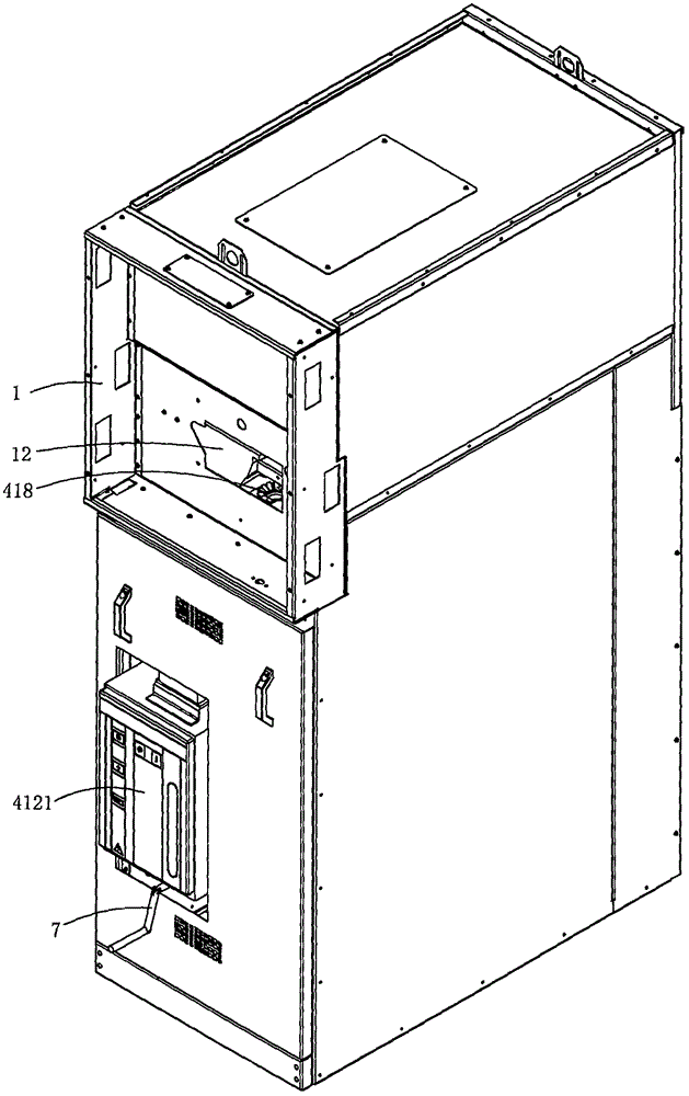
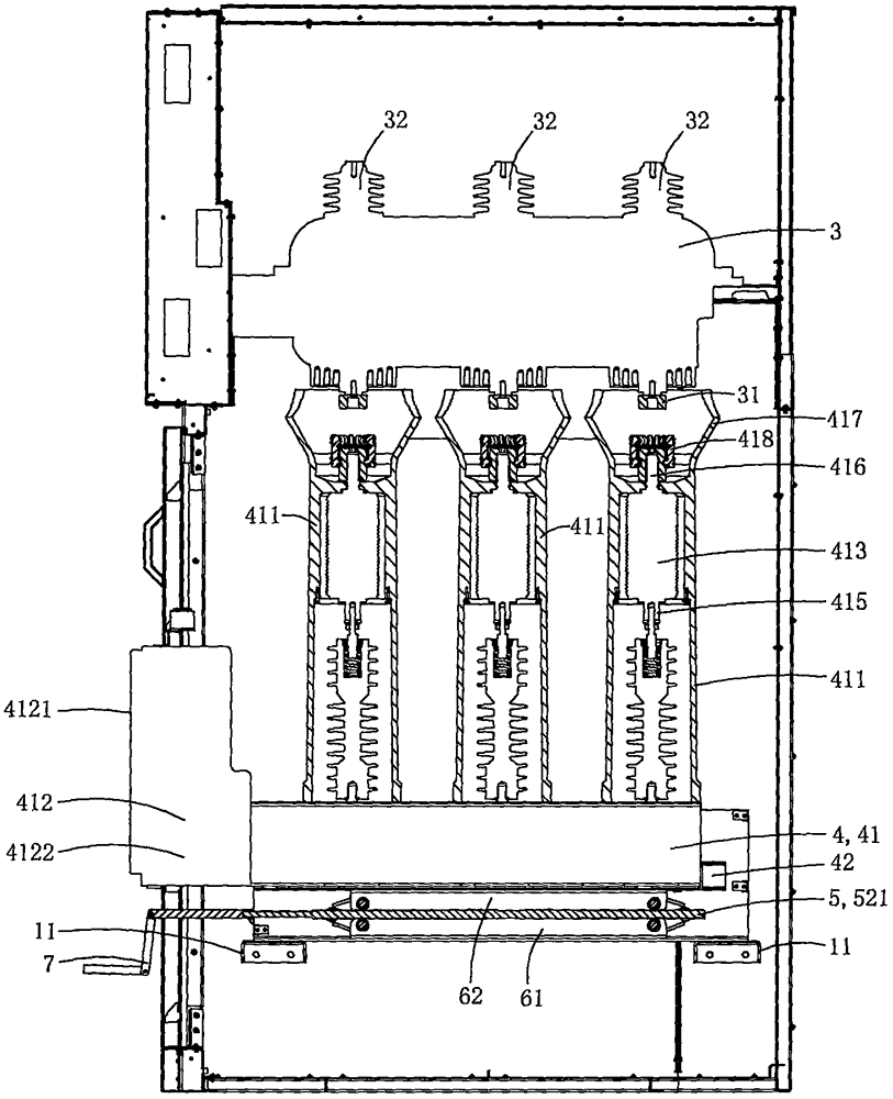
[0030] Figure 1 to Figure 9 One specific embodiment of the invention is shown.

[0031] This embodiment is a kind of high voltage switchgear, see Figure 1 to Figure 9 As shown, it includes a cabinet body 1, a jack-up vacuum circuit breaker 2 and a power access device 3.

[0032] The jack-up vacuum circuit breaker 2 includes a side-mounted vacuum circuit breaker 4 and a jacking device 5 for driving the side-mounted vacuum circuit breaker 4 to reciprocate along the vertical direction;

[0033] The side-mounted vacuum circuit breaker 4 includes a vacuum circuit breaker body 41 and a base 42. The vacuum circuit breaker body includes a three-phase pole 411 and a side-mounted operating mechanism 412; each phase pole is provided with a vacuum set along the vertical direction. The switching tube 413 and the side-out terminal 414; the moving contact 415 of each vacuum switching tube is on the bottom, and the static contact 416 is on the top; each side-out terminal 414 is electrical...


PUM


Abstract

The present invention discloses a high-voltage switch cabinet. The high-voltage switch cabinet includes a cabinet body and a jacking type vacuum circuit breaker, wherein the jacking type vacuum circuit breaker comprises a side-mounted vacuum circuit breaker and a jacking device, wherein the side-mounted vacuum circuit breaker comprises a vacuum circuit breaker body and a base, wherein the bottom of the vacuum circuit breaker body is arranged in the base, the vacuum circuit breaker body comprises three phases of electrode columns and a side-mounted type operation mechanism, wherein the side-mounted operation mechanism comprises an operation panel arranged on the cabinet body of the switch cabinet, and an executing mechanism used for driving three vacuum switch tubes to be switched on and switched off synchronously. The high-voltage switch cabinet is characterized in that the top ends of the electrode columns are provided with insulation protection bowls, wherein each of the insulation protection bowls has a tapered cavity; the top of each of static contacts is provided with a plum blossom type contact seat, wherein the plum blossom type contact seat is located at the center of the bottom of the corresponding insulation protection bowl; and the tops of the plum blossom type contact seats are lower than the top ends of the insulation protection bowls. The overall width of the high-voltage switch cabinet of the present invention can be reduced, and electrical insulation between phases can be enhanced.

Description

technical field [0001] The invention belongs to the technical field of switch cabinets, and in particular relates to a high-voltage switch cabinet. Background technique [0002] Existing switch cabinets have problems such as bulky size, complex structure, low protection level, complicated and unreliable operation interlocking, etc. Existing handcart switch cabinets generally adopt mid-mounted installation, such as KYN28 mid-mounted switch cabinet, which uses high-voltage The three-phase main circuit of the circuit breaker is arranged horizontally, and the circuit breaker can be pushed forward through the operation of the chassis car at the bottom of the circuit breaker. The horizontal layout of the main circuit of the phase leads to a large cabinet width, and the forward and backward movement of the handcart requires a certain stroke, resulting in a deep cabinet, so it occupies a large area; in addition, the upper and lower pairs of contact boxes are located in the middle of...

Claims


Application Information

Patent Timeline
IPC IPC(8): H02B11/20H02B11/02H02B1/30
CPCH02B1/306H02B11/02H02B11/20
Inventor 郑逸扬郑文秀
Owner XINERDE TECH
Learn More