Multi-side pressing type intermediate quick energy-saving conductive connector

A technology of conductive joints and conductive heads, which is applied in the direction of conductive connections, circuits, connections, etc., can solve problems such as power loss, locking screws that are easy to fall out, and long time for connecting wires, etc., and achieve the effect of safe use

Inactive Publication Date: 2017-05-17
SHAOGUAN FANGSHENG ELECTRIC EQUIP CO LTD
View PDF16 Cites 5 Cited by
  • Summary
  • Abstract
  • Description
  • Claims
  • Application Information

AI Technical Summary

Problems solved by technology

This method requires two steps to lock the metal wire of the wire, the operation is complicated, the time to connect the wire is long, the locking force is uneven, and the clamping force is not good, resulting in power loss, and the locking screw is easy to fall out. It is not conducive to the application when working at heights

Method used


Image

  • Multi-side pressing type intermediate quick energy-saving conductive connector
  • Multi-side pressing type intermediate quick energy-saving conductive connector
  • Multi-side pressing type intermediate quick energy-saving conductive connector

Examples


Embodiment 1

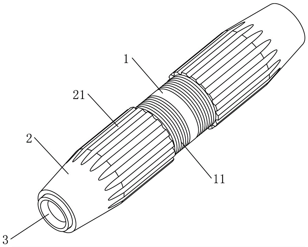
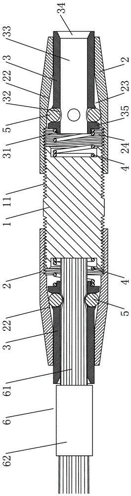
[0028] Embodiment one, see figure 1 and figure 2 As shown, a multi-faceted top-pressing type intermediate fast energy-saving conductive joint includes an intermediate conductive head 1, and the intermediate conductive head 1 is provided with two externally threaded ends 11, and the externally threaded ends 11 are provided with a conductive wire locking device, which is electrically conductive The wire locking device includes an outer lock nut 2, and the outer lock nut 2 is provided with a sleeve hole 23 passing through its two ends, and one end of the sleeve hole 23 is provided with an internal thread 24, and the internal thread 24 is threadedly connected with the external thread end 11. The conductive wire locking device also includes an inner threading tighter sleeve 3 and a plurality of crimping tops 5; the inner threading tighter sleeve 3 is provided with a threading hole 33, and one end of the threading hole 33 leads to the outside of the inner threading tighter sleeve 3...

Embodiment 2

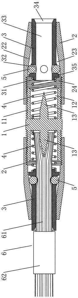
[0036] Embodiment two, see figure 1 and image 3As shown, a multi-faceted top-pressing type intermediate fast energy-saving conductive joint includes an intermediate conductive head 1, and the intermediate conductive head 1 is provided with two externally threaded ends 11, and the externally threaded ends 11 are provided with a conductive wire locking device, which is electrically conductive The wire locking device includes an outer lock nut 2, and the outer lock nut 2 is provided with a sleeve hole 23 passing through its two ends, and one end of the sleeve hole 23 is provided with an internal thread 24, and the internal thread 24 is threadedly connected with the external thread end 11. The conductive wire locking device also includes an inner threading tighter sleeve 3 and a plurality of crimping tops 5; the inner threading tighter sleeve 3 is provided with a threading hole 33, and one end of the threading hole 33 leads to the outside of the inner threading tighter sleeve 3. ...


PUM


Abstract

The invention relates to a multi-side pressing type intermediate quick energy-saving conductive connector, comprising an intermediate conductive head with at least two external-thread ends, each external-thread end is provided with a conductive wire locking device, each conductive wire locking device comprises an external locking nut, each external locking nut is provided with a socket hole running through its two ends, one end of each socket hole is provided with an internal thread in threaded connection to the corresponding external-thread end, each conducive wire locking device also comprises an internal pass tension sleeve and a plurality of press balls, each internal pass tension sleeve is provided with a wire hole inside, one end of each wire hole leads to the outer end of the corresponding internal pass tension sleeve, the wall of each internal pass tension sleeve is provided with through holes corresponding to the corresponding press balls, and the through holes are communicated with the outer wall of the corresponding internal pass tension sleeve and the corresponding wire hole; the press balls are arranged in the through holes and raised out of the through holes; the external locking nuts sleeve the internal pass tension sleeves, and the inner wall of the socket hole of each external locking nut is provided with a pressing conical face corresponding to the through hole distribution range. The multi-side pressing type intermediate quick energy-saving conductive connector has the advantages of good locking force reliability, good operational simplicity and convenience, reusability and the like.

Description

technical field [0001] The invention relates to an intermediate conductive joint for electric conduction connection, in particular to a multi-faced pressing type intermediate fast energy-saving conductive joint. Background technique [0002] The current intermediate conductive joint for electric conductive connection includes an intermediate conductive head, and the two ends of the intermediate conductive head are provided with wire clips. , to achieve wire clamping. However, the structure is complicated to install, and it is difficult to disassemble the wire after connection, and the wire cannot be put into use again after disassembly (if the terminal conductive lug is used again, it is easy to break). In addition, because the high-voltage cables are generally bare wires, the length of the hydraulic pliers is relatively long. If the wires are connected under live conditions, the hydraulic pliers are likely to touch other phase wires and cause short-circuit accidents. There...

Claims


Application Information

Patent Timeline
Patent Type & Authority Applications(China)
IPC IPC(8): H01R4/00H01R4/48
CPCH01R4/48H01R4/4863H01R4/54
Inventor 曹孝培
Owner SHAOGUAN FANGSHENG ELECTRIC EQUIP CO LTD
Why Eureka
Try Eureka