
Intelligent ETC lane toll collection system and intelligent ETC lane toll collection method based on phased array

A phased array, lane technology, applied in electromagnetic radiation induction, instruments, induction record carriers, etc., can solve the problems of low antenna recognition accuracy, affecting transaction reliability, and interfering with near-area antenna work, to improve traffic processing efficiency , the effect of speeding up the transaction and avoiding the interference of following cars

Inactive Publication Date: 2017-05-17
GUANGZHOU HUAGONG INFORMATION SOFTWARE
View PDF7 Cites 6 Cited by
  • Summary
  • Abstract
  • Description
  • Claims
  • Application Information

AI Technical Summary

Problems solved by technology

However, when the system is switched to work with the near-field antenna, the far-field antenna is also required to be in an open state, causing the OBU of the far-field vehicle to be activated by the far-field antenna, and the activated OBU is easy to trade with the working near-field antenna, thereby allowing the vehicle to pass. Untraded vehicles in the near area affect the reliability of the transaction. At the same time, the radiation unit of the antenna in the far area interferes with the work of the antenna in the near area, resulting in low identification accuracy of the antenna.

Method used


Image

  • Intelligent ETC lane toll collection system and intelligent ETC lane toll collection method based on phased array
  • Intelligent ETC lane toll collection system and intelligent ETC lane toll collection method based on phased array
  • Intelligent ETC lane toll collection system and intelligent ETC lane toll collection method based on phased array

Examples


Embodiment 1

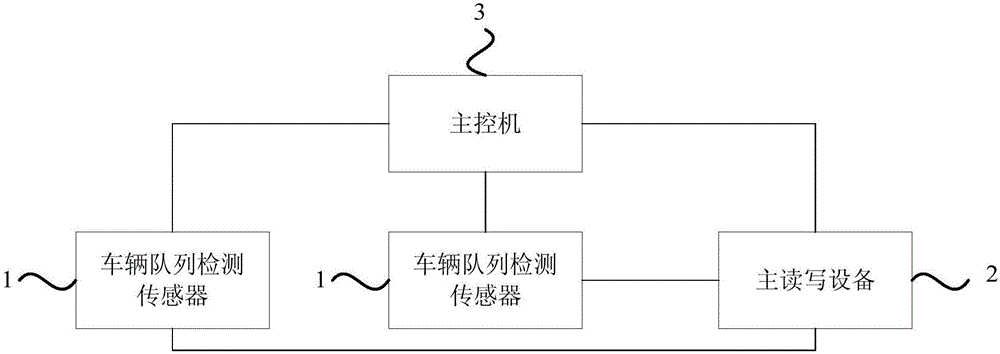
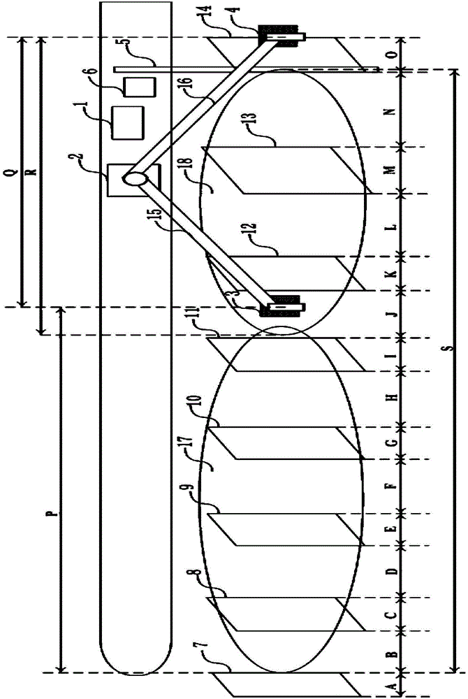
[0042] Figure 1A A schematic structural diagram of a phased array-based intelligent ETC lane toll system provided by Embodiment 1 of the present invention. This embodiment can be applied to lane tolls. The system can be implemented by software and hardware. The system includes:

[0043] At least two vehicle queue detection sensors 1 are arranged at intervals along the main identification area of ​​the toll channel, and are used to detect the position information of vehicles passing through the main identification area;

[0044] The main read-write device 2 is arranged on the side of the main identification area adjacent to the vehicle railing along the toll channel. The main read-write device 2 includes a phased array antenna for transmitting antenna signals. Carry out communication identification on the tag of the vehicle in order to obtain the charging information and tag location information of the vehicle;

[0045] The main control machine 3 is connected with the vehicle ...

Embodiment 2

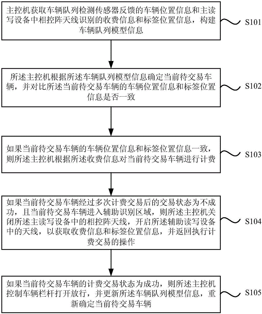
[0060] figure 2 It is a flow chart of a phased array-based intelligent ETC lane tolling method in Embodiment 2 of the present invention. This embodiment can be applied to a phased array-based intelligent ETC lane toll system for lanes. The method includes:

[0061] S101. The main control computer obtains the vehicle position information fed back by the vehicle platoon detection sensor, the charging information and tag position information identified by the phased array antenna in the main read-write device, and constructs vehicle platoon model information.

[0062] Preferably, step S101 includes:

[0063] The information acquired by the main control unit also includes vehicle license plate information, vehicle and electronic tag binding information, vehicle passage information, vehicle speed information, vehicle length information and vehicle quantity information.

[0064] Specifically, the phased array antenna on the main read-write device and the antenna on the auxiliary r...

Embodiment 3

[0078] image 3 It is a method flow chart of a preferred mode of a phased array-based intelligent ETC lane tolling method provided by Embodiment 3 of the present invention. This embodiment is based on the foregoing embodiments and provides an optimal solution for failure to enable the auxiliary reading and writing device. Specifically, if the transaction status of the current vehicle to be traded is unsuccessful after multiple billing transactions, and the current vehicle to be traded enters the auxiliary identification area, the main control unit turns off the phase control in the main read-write device. Array antenna, turn on the antenna in the auxiliary read-write device to obtain charging information and tag location information, and return to perform the operation of charging transactions, specifically including:

[0079] If the main control computer fails to open the antenna in the auxiliary read-write device, the vehicle currently to be traded will withdraw from the res...


PUM


Abstract

The embodiments of the invention disclose an intelligent ETC lane toll collection system and an intelligent ETC lane toll collection method based on a phased array. The system comprises at least two vehicle queue detection sensors, main reading and writing equipment, and a main control machine. The main control machine acquires vehicle position information fed back by the vehicle queue detection sensors and toll collection information and tag position information identified by a phased array antenna in the main reading and writing equipment, and constructs vehicle queue model information. When the vehicle position information of a current vehicle under transaction is consistent with the tag position information, a billing transaction is conducted. If the billing transaction status indicates that transaction fails, backup reading and writing equipment is started for billing transaction. If the billing transaction status indicates that transaction succeeds, the main control machine opens a barrier gate to release the vehicle, and the vehicle queue model information is updated. Through the technical scheme of the invention, the transaction efficiency of the main identification area, the processing efficiency of vehicle passing and the reliability of billing transaction are improved, and the flexibility of system construction is increased.

Description

technical field [0001] Embodiments of the present invention relate to lane toll collection technology, in particular to a phased array-based intelligent ETC lane toll collection system and method. Background technique [0002] Due to my country's special national conditions, congestion is a major shackle in the development of my country's transportation. As one of the most advanced road and bridge toll methods in the world, the mission of the Electronic Toll Collection (ETC) system is to use intelligent technology to change this situation. . Through the microwave communication between the on board unit (OBU) installed on the inside of the front windshield of the vehicle and the roadside antenna unit erected on the side of the ETC lane of the toll station, information is exchanged during the driving process of the vehicle. Thereby reaching the purpose that the vehicle can pay the road and bridge toll without stopping when passing through the road and bridge toll station, and ...

Claims


Application Information

Patent Timeline
Patent Type & Authority Applications(China)
IPC IPC(8): G07B15/06G06K7/10
CPCG06K7/10128G07B15/063
Inventor 李计管徐晓帆谢海强王锐煌张堂隆冯顺萍
Owner GUANGZHOU HUAGONG INFORMATION SOFTWARE
Learn More