
Oiler

A technology for oiling machines and oil tanks, which is applied to mechanical equipment, gear lubrication/cooling, belts/chains/gears, etc., and can solve problems such as oil stains being coated in keyways

Active Publication Date: 2019-01-29
CHONGQING SUTENG MACHINERY MFG
View PDF5 Cites 0 Cited by
  • Summary
  • Abstract
  • Description
  • Claims
  • Application Information

AI Technical Summary

Problems solved by technology

[0006] The present invention intends to provide an oiler to solve the problem that the existing oiler is easy to coat the oil dirt in the keyway

Method used


Image

  • Oiler
  • Oiler

Examples


Embodiment Construction

[0028] The present invention will be described in further detail below by means of specific embodiments:

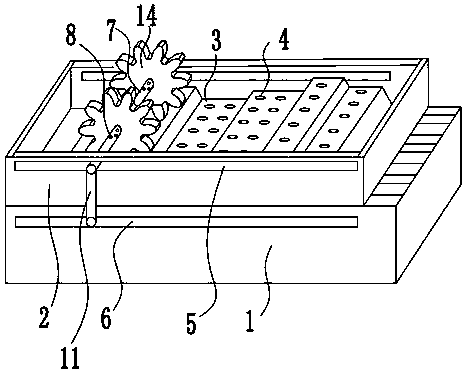
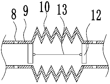
[0029] The reference signs in the drawings of the description include: fuel tank 1, oil pool 2, pool bottom 3, leakage hole 4, first slideway 5, second slideway 6, rotating shaft 7, spray hole 8, straight pipe 9, corrugated Pipe 10, oil delivery pipe 11, baffle plate 12, connecting rod 13, gear 14.

[0030] Such as figure 1 and figure 2 As shown, the oiler includes an oil tank 1, an oil pool 2 and an oil delivery pipe 11 connecting the oil tank 1 and the oil pool 2; The oil pool 2 is supported by the support net without affecting the passage of the oil leaked from the oil leakage hole.

[0031] The oil pool 2 is provided with an ups and downs pool bottom 3 that can be touched by the gear 14. The pool bottom 3 is provided with a plurality of leakage holes 4 for oil leakage; the pool walls on both sides of the pool bottom 3 are provided with 3 first slideways 5 arrange...


PUM


Abstract

The invention discloses an oil application machine. The oil application machine comprises an oil tank, an oil pool and an oil conveying pipe, wherein the oil conveying pipe enables the oil tank to communicate with the oil pool. The oil pool is arranged above the oil tank. A pool bottom which can be touched by gears and rises and falls is arranged in the oil pool. Leakage holes used for leaking oil are formed in the pool bottom. First slide ways are horizontally arranged on the pool walls of the two sides of the pool bottom in the rising-and-falling direction of the pool bottom. A rotating shaft which rotates along the first slide ways is connected between the first slide ways. Protrusions used for fixing the gears are arranged on the rotating shaft. The rotating shaft is a flexible shaft and provided with spray holes used for spraying oil to the gears. The rotating shaft communicates with the oil conveying pipe. By means of the oil application machine, oil application conducted on key grooves is effectively avoided.

Description

technical field [0001] The invention relates to the field of gear processing, in particular to an oiler. Background technique [0002] Oiler is an essential production tool in machinery manufacturing. Before leaving the factory, mechanical parts must be oiled by an oiler, which not only plays a role in lubrication, but more importantly, isolates the contact between air and the surface of metal parts to prevent corrosion and oxidation of metal parts. [0003] Gears are the most commonly used metal parts. In addition to the exposed teeth for meshing, the most important thing in the gear is the keyway arranged at the center of the gear shaft. The gear is connected with the rotating shaft that drives the gear to rotate through the keyway. If there is a deviation in the size of the keyway, it will affect the firmness of the connection between the gear and the rotating shaft. It is very likely that the rotating shaft rotates and the gears do not rotate synchronously, and even ...

Claims


Application Information

Patent Timeline
Patent Type & Authority Patents(China)
IPC IPC(8): F16H57/04
CPCF16H57/042F16H57/0434
Inventor 王全中
Owner CHONGQING SUTENG MACHINERY MFG
Learn More