
Two-way oil inlet long-needle-valve hole-plate type electronic control fuel injector without static leakage

An electronically controlled fuel injection and fuel injector technology, which is applied to machines/engines, fuel injection devices, engine components, etc., can solve problems such as the influence of the stability of the fuel injection device, increase the power consumption of the high-pressure fuel pump, and waste high-pressure fuel. The effect of reducing soot emissions and fuel consumption, reducing fuel pump power consumption, and reducing fuel consumption

Inactive Publication Date: 2017-05-17
HARBIN ENG UNIV
View PDF9 Cites 0 Cited by
  • Summary
  • Abstract
  • Description
  • Claims
  • Application Information

AI Technical Summary

Problems solved by technology

In the actual working process of a diesel engine equipped with a high-pressure common rail system, the electronically controlled fuel injector in the high-pressure common rail system has the disadvantage of fuel leakage. The fuel leakage caused by the fit gap is static leakage, and the other part of the fuel leakage is caused by a part of the fuel in the cylinder not participating in the injection in the cylinder during the operation of the electronically controlled fuel injector, and directly returning to the low-pressure fuel tank through the low-pressure fuel passage. The dynamic leakage of fuel, the leakage of fuel in actual work causes the waste of high-pressure fuel, increases the power consumption of the high-pressure fuel pump, and has a certain impact on the stability of the fuel injection device

Method used


Image

  • Two-way oil inlet long-needle-valve hole-plate type electronic control fuel injector without static leakage
  • Two-way oil inlet long-needle-valve hole-plate type electronic control fuel injector without static leakage
  • Two-way oil inlet long-needle-valve hole-plate type electronic control fuel injector without static leakage

Examples


Embodiment Construction

[0016] The present invention is described in more detail below in conjunction with accompanying drawing example:

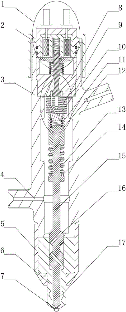
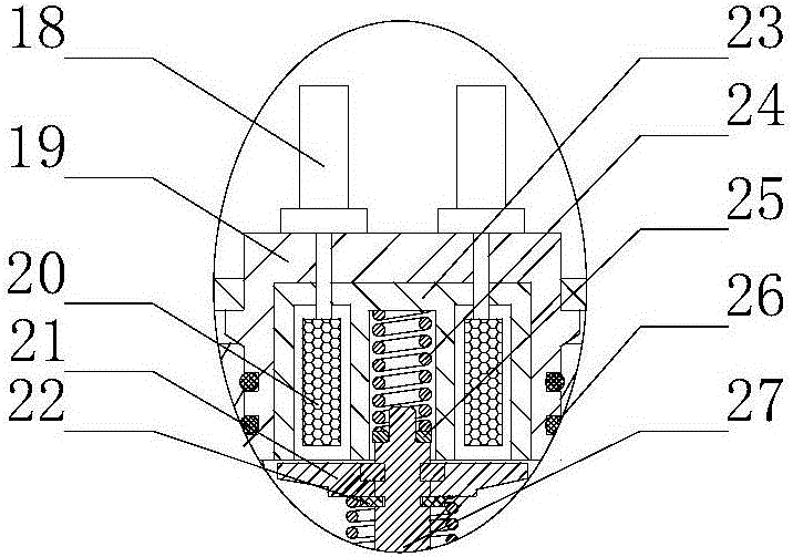
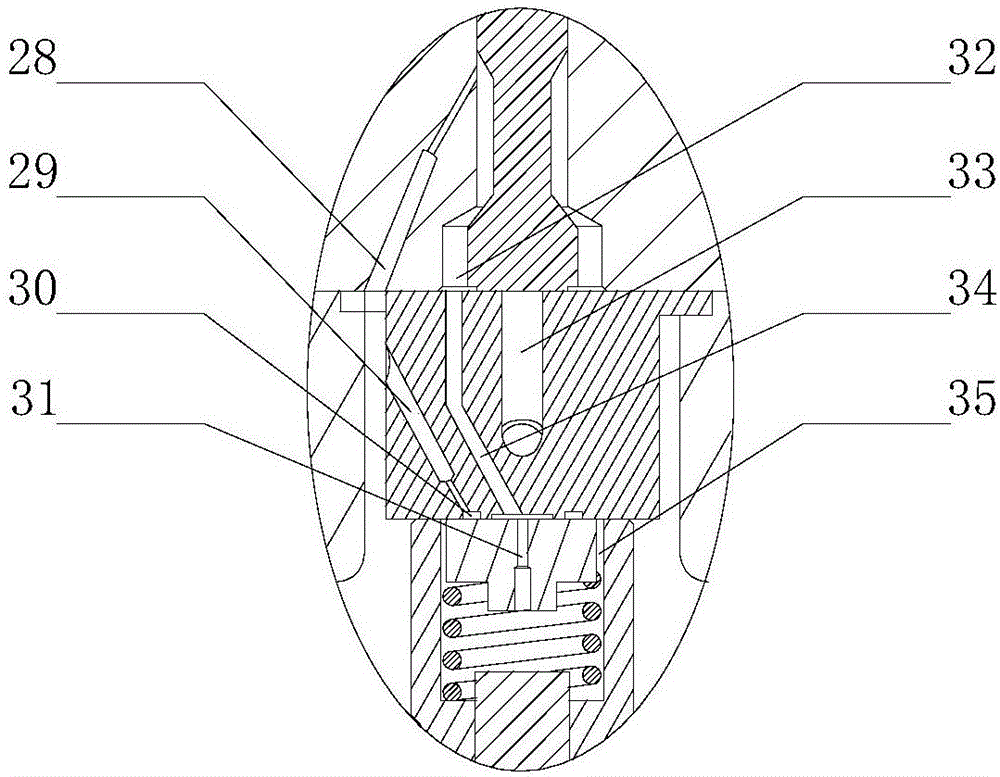
[0017] combine Figure 1-3 , the present invention is a two-way oil-inlet long-needle valve orifice-plate electronically controlled fuel injector without static leakage, which consists of a solenoid valve assembly 1, a fastening shell 2, an injector body 3, a tight cap 5, a nozzle 6, Electromagnetic valve seat 8, middle block 9, control panel 10, control panel return spring 11, limit sleeve 12, long needle valve return spring 13, long needle valve return spring seat 14 and long needle valve 15 form. The solenoid valve assembly 1 is arranged on the solenoid valve seat 8. After the arrangement is completed, it is installed from the top of the injector body 3 together. The solenoid valve assembly 1 includes a terminal post 18, a solenoid valve body 19, a coil 20, an armature 21, a stop Moving ring 22, iron core 23, valve stem return spring 24, valve stem return spri...


PUM


Abstract

The invention provides a two-way fuel inlet long-needle-valve hole-plate type electronic control fuel injector without static leakage. The two-way fuel inlet long-needle-valve hole-plate type electronic control fuel injector comprises an electromagnetic valve assembly, a fuel injector body, a nozzle, a long needle valve, a limiting sleeve, a control plate, a middle block and an electromagnetic valve seat. A fuel cavity is formed in the fuel injector body and fully filled with high-pressure fuel, so that the upper and lower ends of each needle valve coupling piece are both in a high pressure environment, the pressure difference of the upper end and the lower end of each needle valve coupling piece is approximate to zero, accordingly fuel leaking, caused by matching gaps between the internal coupling pieces, of the electronic control fuel injector is avoided, and no static leakage of the fuel is achieved; and additionally, the control plate is arranged in a control cavity, in the earlier period of fuel leaking of the control cavity, an annular fuel inlet gauge hole formed in the middle block is closed through the control plate, so that the dynamic fuel leakage amount generated at the time of practical working of the electronic control fuel injector can be reduced effectively, accordingly fuel loss is reduced, fuel pump power consumption is reduced, the working stability of a device is improved, and the fuel injection characteristic is improved.

Description

technical field [0001] The invention relates to an electromagnetically controlled fuel injector, in particular to an electromagnetically controlled fuel injector for a high-pressure common rail. Background technique [0002] As an advanced fuel injection system in the field of diesel engine fuel injection, the high-pressure common rail system has its own excellent characteristics, that is, the injection pressure generation is separated from the injection process, and it can accurately and flexibly control the fuel injection quantity and fuel injection timing, which improves the performance of the diesel engine. Economical, emission characteristics and other performances have attracted widespread attention. In the actual working process of a diesel engine equipped with a high-pressure common rail system, the electronically controlled fuel injector in the high-pressure common rail system has the disadvantage of fuel leakage. The fuel leakage caused by the fit gap is static le...

Claims


Application Information

Patent Timeline
Patent Type & Authority Applications(China)
IPC IPC(8): F02M51/06F02M61/10F02M61/16F02M61/18
CPCF02M51/061F02M61/10F02M61/16F02M61/18
Inventor 范立云彭文博石勇李文辉
Owner HARBIN ENG UNIV
Learn More