
Spring double-face polishing device capable of carrying out feeding automatically

A technology of automatic feeding and double-sided grinding, which is applied in the direction of grinding machine, grinding feed movement, grinding workpiece support, etc., can solve the problems affecting the efficiency, affecting the beauty of the spring and the accuracy of the installation, and the injury of the operator, so as to reduce the Work load, productivity improvement effect

Active Publication Date: 2017-05-17
ZHEJIANG HUAWEI SPRING
View PDF9 Cites 16 Cited by
  • Summary
  • Abstract
  • Description
  • Claims
  • Application Information

AI Technical Summary

Problems solved by technology

[0004] At present, when the spring leaves the factory, because the surface of the steel wire of the spring itself is not smooth or the spring bending tool is not smooth, the end face of the spring will have burrs. The operator’s hands cause injury, so it is necessary to grind the end face of the spring. Now the spring is polished to a single end face and after the blanking, the other end face is reversely ground, and the material is manually loaded by a single spring, which is inefficient and affects the benefit. Grinding the two end faces can improve production efficiency, which requires the spring to be erected for loading. The traditional manual loading operation will increase the workload of workers. Therefore, an automatic loading spring double-sided grinding device is proposed.

Method used


Image

  • Spring double-face polishing device capable of carrying out feeding automatically
  • Spring double-face polishing device capable of carrying out feeding automatically
  • Spring double-face polishing device capable of carrying out feeding automatically

Examples


Embodiment Construction

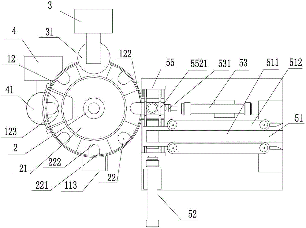
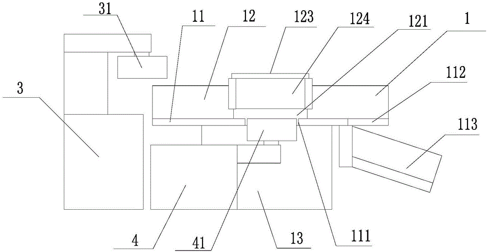
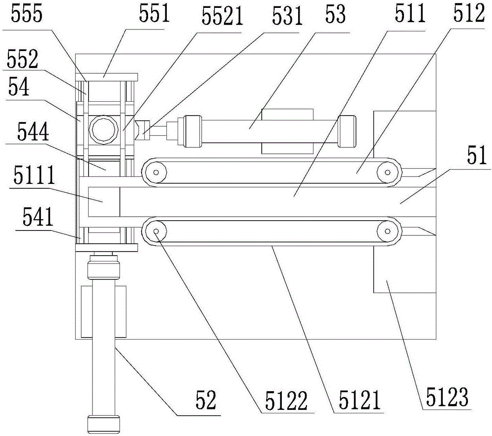
[0025] see Figure 1 to Figure 5 , the present invention is an automatic feeding spring double-sided grinding device, comprising a frame 1, a rotating feeding seat 2, an upper end surface grinding mechanism 3, a lower end surface grinding mechanism 4 and an automatic feeding device 5. A fixed chassis 11 is provided, the outer periphery of the fixed chassis 11 is provided with a blocking frame 12, a mounting cavity 114 is opened at the center of the fixed chassis 11, and a power box 13 is arranged below the fixed chassis 11, and the power box The drive shaft of 13 passes through the installation cavity 114 and is matched with the rotary feeding base 2. The rotary feeding base 2 is provided with a turntable 21, and a plurality of embedding grooves 22 are opened on the rotary table 21, and the embedding grooves 22 penetrate through the rotary table. 21. An automatic feeding device 5, an upper end surface grinding mechanism 3, a lower end surface grinding mechanism 4 and an unload...


PUM


Abstract

The invention discloses a spring double-face polishing device capable of carrying out feeding automatically. The spring double-face polishing device comprises a rack, a rotary feeding base, an upper end face polishing mechanism, a lower end face polishing mechanism and an automatic feeding device. The rack is provided with a fixing chassis. A blocking frame is arranged on the periphery of the fixing chassis. A rotary disc is arranged on the rotary feeding base. A plurality of embedding grooves are formed in the rotary disc. The automatic feeding device, the upper end face polishing mechanism, the lower end face polishing mechanism and a discharging frame are sequentially arranged on the outer side of the rotary feeding base in the periphery direction. The automatic feeding device is provided with a feeding sliding base. A spring chute is formed in the feeding sliding base. The upper end face polishing mechanism is provided with a first abrasion wheel. The lower end face polishing mechanism is provided with a second abrasion wheel. An air cylinder is utilized for driving the sliding base to be conveyed to the feeding position, a spring is pushed into the rotary feeding base through the air cylinder, the vertical spring is fed automatically, the two abrasion wheels polish the upper end face and the lower end face of the spring sequentially, and the production efficiency can be improved.

Description

[0001] 【Technical field】 [0002] The invention relates to the technical field of automatic assembly, in particular to the technical field of a spring double-sided grinding device for automatic feeding. [0003] 【Background technique】 [0004] At present, when the spring leaves the factory, because the surface of the steel wire for making the spring itself is not clean or the spring bending tool is not smooth, the end face of the spring will have burrs. The operator's hands cause injury, so the end face of the spring needs to be polished. Now, after the spring is polished to a single end face, the other end face is polished in the reverse direction. The feeding is manual feeding of a single spring, which is inefficient and affects the efficiency. Grinding the two end faces can improve the production efficiency, which requires the spring to be erected for feeding. The traditional manual feeding operation will increase the workload of the workers. Therefore, an automatic feeding ...

Claims


Application Information

Patent Timeline
IPC IPC(8): B24B7/17B24B41/00B24B41/06B24B27/00
CPCB24B7/167B24B7/17B24B27/0023B24B27/0069B24B41/005B24B41/06
Inventor 寿新涛金雷
Owner ZHEJIANG HUAWEI SPRING
Learn More