Method and apparatus for allocating power levels to a transmission in a digital subscriber line network

A digital subscriber line and subscriber line technology, applied in the directions of power management, current supply device, line transmission components, etc., can solve problems such as crosstalk of the first subscriber line, and achieve the effect of increasing bandwidth, data rate, and utilization rate

Active Publication Date: 2017-05-10
BRITISH TELECOMM PLC
View PDF4 Cites 5 Cited by
  • Summary
  • Abstract
  • Description
  • Claims
  • Application Information

AI Technical Summary

Problems solved by technology

If not (i.e. if both signals are sent at the same power level), the signal on the second subscriber line will cause a lot of crosstalk on the first subscriber line

Method used


Image

  • Method and apparatus for allocating power levels to a transmission in a digital subscriber line network
  • Method and apparatus for allocating power levels to a transmission in a digital subscriber line network
  • Method and apparatus for allocating power levels to a transmission in a digital subscriber line network

Examples


Embodiment Construction

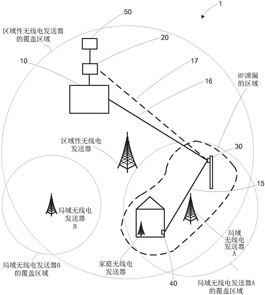
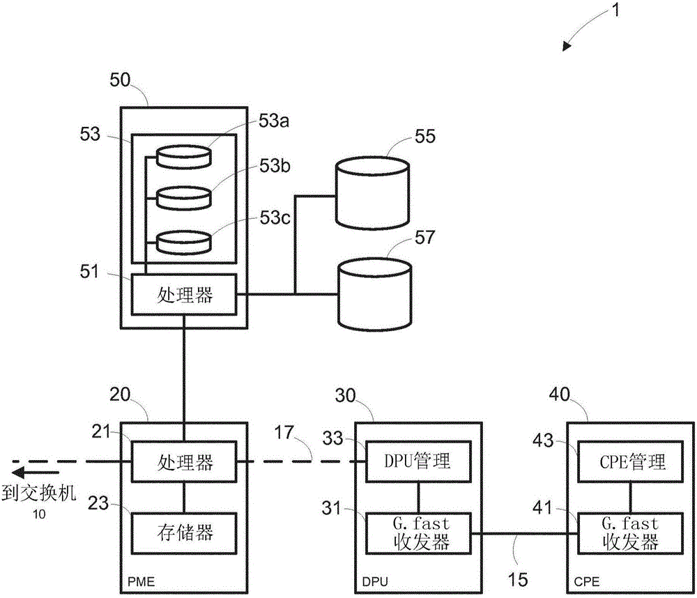
[0032] will now refer to Figure 1 to Figure 2 An embodiment of the Digital Subscriber Line (DSL) network 1 of the present invention is described. figure 1 An overview of a DSL network 1 comprising a switch 10 , a permanent management entity (PME) 20 , a drop point unit (DPU) 30 and a customer premises equipment (CPE) 40 is illustrated. The switch 10 , PME 20 , DPU 30 and CPE 40 are all connected by a subscriber line consisting of a fiber optic section 16 from the switch 10 to the DPU 30 and a copper section 15 from the DPU 30 to the CPE 40 . The skilled person will appreciate that switches 10, PME 20 and DPU 30 will generally have a one-to-many relationship with network elements lower in the DSL network hierarchy, but for simplicity a one-to-one mapping is used in this description.

[0033] figure 1 Also shown is a mask builder 50 connected to the PME 20 in this embodiment. Such as figure 2 As shown in more detail in , the mask builder 50 includes a processor 51, a mask ...


PUM


Abstract

The invention relates to a method, and a device for performing said method, for allocating power levels to a transmission in a DSL network, the method comprising the steps of: identifying a first and second geographical region as being associated with a subscriber line in the DSL network; defining a first spectral mask having a first set of power levels over a range of frequencies, wherein the first set of power levels are tailored according to a Radio Frequency, RF, environment of the first geographical region; defining a second spectral mask having a second set of power levels over the range of frequencies, wherein the second set of power levels are tailored according to an RF environment of the second geographical region; and constructing a transmit spectral mask for the subscriber line, the transmit spectral mask based on a combination of the first and second spectral masks, including, for each frequency in the range of frequencies, using the minimum power level for that frequency from the first and second spectral masks.

Description

technical field [0001] The present invention relates to methods and arrangements for allocating power levels for transmissions in a DSL network. In particular, the invention relates to the use of spectral masks to assign power levels within frequency ranges for transmissions in DSL networks. Background technique [0002] Digital Subscriber Line (DSL) is a common technology for providing digital communications. In early DSL deployments, the broadband connection to the customer premises consisted of a DSL connection extended over an existing twisted-pair copper subscriber line between two DSL modems located at the switch (central office in US terminology) and the customer premises, respectively. to provide. With the development of DSL technology, most of each DSL connection is through the extension switch and another element in the access network, such as the street box (for fiber to the node deployment) or drop point unit (DPU) (for fiber to the drop point deployment)) to ...

Claims


Application Information

Patent Timeline
Patent Type & Authority Applications(China)
IPC IPC(8): H04M11/06
CPCH04M11/062H04B3/46H04W52/00Y02D30/70H04M19/001
Inventor 特雷弗·林尼I·霍斯利T·莫斯曼
Owner BRITISH TELECOMM PLC
Why Eureka
Try Eureka