
Cylinder head for a compressor with particularly efficient air cooling

A compressor and air technology, applied in the direction of mechanical equipment, machines/engines, liquid variable capacity machines, etc., can solve the problems of pressure loss and structural costs, and achieve the effects of small wall thickness, efficient cooling, and reduced surface temperature

Inactive Publication Date: 2017-05-10
KNORR BREMSE SYST FUER NUTZFAHRZEUGE GMBH
View PDF11 Cites 2 Cited by
  • Summary
  • Abstract
  • Description
  • Claims
  • Application Information

AI Technical Summary

Problems solved by technology

Here, the pressure loss caused by the long lines and the structural outlay caused by the pressure lines themselves are disadvantageous

Method used


Image

  • Cylinder head for a compressor with particularly efficient air cooling
  • Cylinder head for a compressor with particularly efficient air cooling

Examples


Embodiment Construction

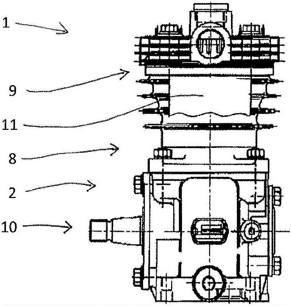
[0025] according to figure 1 , the compressor 2 has a cylinder head 1 and a piston housing 8 , wherein a valve plate 9 is arranged between the piston housing 8 and the cylinder head 1 . The compressor 2 is driven via a shaft 10 . The piston housing 8 is sectioned near the valve plate 9 so that the piston chamber 11 is visible. A piston, not shown here, moves axially up and down inside the piston chamber 11 .

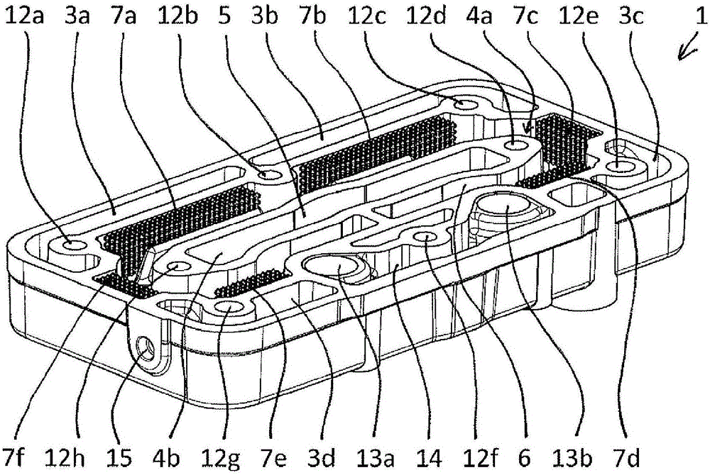
[0026] according to figure 2 , the cylinder head 1 has four coolant guide areas 3a-3d and two air guide areas 4a, 4b. Four coolant guide areas 3a-3d are arranged substantially around the two air guide areas 4a, 4b, wherein the four coolant guide areas 3a-3d directly adjoin the air guide area 4a in order to cool the compressed air. The valve plate 9 is also meandered through by coolant guide channels, not shown here.

[0027] The two air conduction areas 4 a , 4 b comprise an air inlet channel 5 for feeding air to be compressed into the compressor 2 and an air outle...


PUM


Abstract

The invention relates to a cylinder head (1) for a compressor (2), comprising at least one coolant-conducting region (3a) and at least two air-conducting regions (4a, 4b), wherein the at least one coolant-conducting region (3a) is arranged at least partially around the at least two air-conducting regions (4a, 4b), wherein, furthermore, the at least two air-conducting regions (4a, 4b) have at least one air-feeding duct (5) for feeding the air to be compressed into the compressor (2) and at least one air-discharging duct (6) for outputting a compressed air which is compressed by the compressor (2). According to the invention, the at least one air-discharging duct (6) comprises an open-pore, metallic cell structure (7).

Description

technical field [0001] The invention relates to a cylinder head for a compressor comprising at least one coolant-guiding area and at least two air-guiding areas, wherein the at least one coolant-guiding area at least partially surrounds the at least two air-guiding areas. The guide area arrangement, wherein the at least two air guide areas also have at least one air introduction duct for feeding the air to be compressed into the compressor and at least one air duct for discharging the compressed air compressed by the compressor Export channels. Background technique [0002] Modern trucks used in rail or road traffic are equipped with several subsystems that consume compressed air. Examples of these subsystems are service brakes and air suspensions that operate with compressed air. The supply of compressed air to the compressed air consumer is effected by means of a compressed air supply comprising a compressor. The ambient air is sucked in by the compressor, compressed an...

Claims


Application Information

Patent Timeline
Patent Type & Authority Applications(China)
IPC IPC(8): F04B39/06F04B39/12
CPCF04B39/064F04B39/125
Inventor A·马克格拉夫T·米特尔施特拉斯
Owner KNORR BREMSE SYST FUER NUTZFAHRZEUGE GMBH
Learn More