
Method and circuit for automatically setting address code between lamps and realizing coexistence with RDM

An address code and automatic coding technology, which is applied to the layout of electric lamp circuits, electric light sources, lighting devices, etc., can solve the problems of cumbersome work in setting addresses, achieve the effect of increasing the automatic coding function and reducing the workload

Inactive Publication Date: 2017-05-10
GUANGZHOU FINEART LIGHTING
View PDF7 Cites 5 Cited by
  • Summary
  • Abstract
  • Description
  • Claims
  • Application Information

AI Technical Summary

Problems solved by technology

When the luminaire has been installed on the stage (sometimes the luminaire is at a higher position on the top of the stage) and the address code needs to be changed, the luminaire without the RDM function requires professionals to climb to the position of the luminaire to reset the address of the luminaire, and the luminaire with the RDM function also needs to be changed. It is necessary to use the console or computer to identify the lamp and then operate on the console or computer to reset the address of the lamp. The work of setting the address is very cumbersome

Method used


Image

  • Method and circuit for automatically setting address code between lamps and realizing coexistence with RDM
  • Method and circuit for automatically setting address code between lamps and realizing coexistence with RDM
  • Method and circuit for automatically setting address code between lamps and realizing coexistence with RDM

Examples


Embodiment Construction

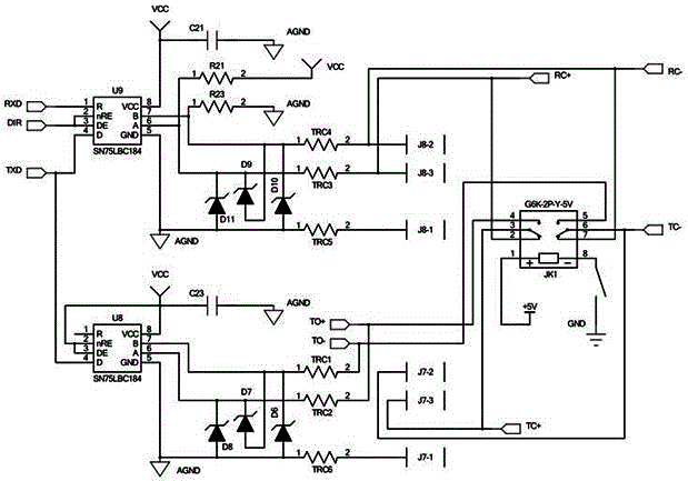
[0021] The present invention is illustrated by taking a lamp as an example, as image 3 As shown, a circuit that can automatically set address codes between lamps and lamps and coexist with RDM, including a console (not shown in the figure), the console communicates with each lamp through the 485 bus, and each lamp includes a A receiving signal IC U9 for receiving console signals, a transmitting signal ICU8 for transmitting address codes, and a series-to-parallel conversion circuit.

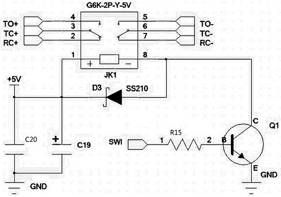
[0022] like figure 2 As shown, the serial-to-parallel conversion circuit includes a relay JK1 and a switch circuit K1 that controls the relay. The switch circuit K1 is composed of an NPN transistor Q1 and a resistor R15. The base voltage Vbe, the model of the relay JK1 is G6K-2P-Y-5V, the pin 1 of the relay is connected to the anode of the capacitor C20 and C19 and then connected to +5V, and the cathode of the capacitor C20 and C19 is connected to the ground; the The pin 8 of the relay is conn...


PUM


Abstract

The invention discloses a method for automatically setting an address code between lamps and realizing coexistence with RDM, and a circuit for realizing the method. After the method is utilized, an automatic coding function is added on the condition of being compatible with a traditional signal wire, and workload in setting the address code of the lamp by a field engineer can be greatly reduced.

Description

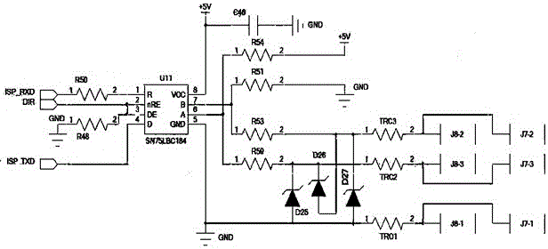
technical field [0001] The invention relates to the technical field of stage lamps, in particular to a method for automatically setting address codes between lamps and coexisting with RDM and a circuit for realizing the method. Background technique [0002] like figure 1 As shown, in the prior art, the main control board of the lamp has only one 485 signal receiving IC U11, and the signal terminals J7 and J8 on the main control board are all connected to the 485 bus in parallel, and various control signals of the console pass through the 485 The bus communicates with the light fixtures. Under the current conditions, if the console or computer wants to control the stage lights, you must first dial the address code for each light fixture. The traditional method is that each light fixture is manually set by a professional; there is another way that the light fixture has RDM communication function, the console or the main control computer can set each lamp through the RDM prot...

Claims


Application Information

Patent Timeline
Patent Type & Authority Applications(China)
IPC IPC(8): H05B37/02
CPCH05B47/18
Inventor 刘建华王斌
Owner GUANGZHOU FINEART LIGHTING
Learn More