Apparatus and method in wireless communication system

A wireless communication system and antenna technology, applied in wireless communication, radio transmission system, radio wave measurement system, etc., can solve the problems of less research, high RF cost, and high technical complexity of the system, so as to reduce costs and reduce mutual interference. , the effect of increasing the achievable data rate

Inactive Publication Date: 2017-05-10
SONY CORP
View PDF11 Cites 9 Cited by
  • Summary
  • Abstract
  • Description
  • Claims
  • Application Information

AI Technical Summary

Problems solved by technology

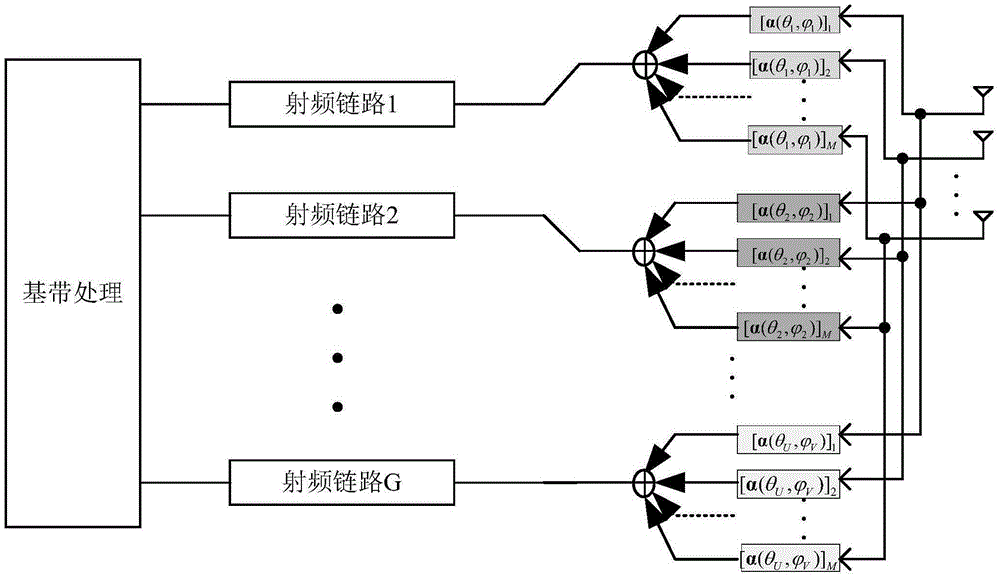
In the existing technology, the 3D beamforming is usually achieved by setting the same number of radio frequency links as the number of antennas. However, under the condition of large-scale deployment of antennas, the cost of radio frequency will become very high, and the technical complexity of the system will also increase. will be high
In order to reduce cost and complexity, hybrid 3D beamforming techniques utilizing fewer RF links in large-scale antenna systems have received great attention, but there are still few studies on this aspect

Method used


Image

  • Apparatus and method in wireless communication system
  • Apparatus and method in wireless communication system
  • Apparatus and method in wireless communication system

Examples


Embodiment Construction

[0045] Exemplary embodiments of the present disclosure will be described below with reference to the accompanying drawings. In the interest of clarity and conciseness, not all features of an actual implementation are described in this specification. It should be understood, however, that in developing any such practical embodiment, many implementation-specific decisions must be made in order to achieve the developer's specific goals, such as meeting those constraints related to the system and business, and those Restrictions may vary from implementation to implementation. Moreover, it should also be understood that development work, while potentially complex and time-consuming, would at least be a routine undertaking for those skilled in the art having the benefit of this disclosure.

[0046] Here, it should be noted that in order to avoid obscuring the present disclosure due to unnecessary details, only the device structure and / or processing steps closely related to the solu...


PUM


Abstract

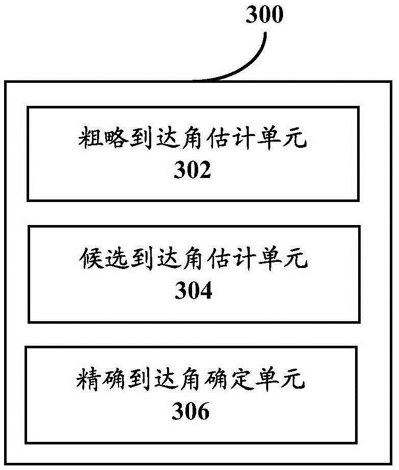
An apparatus and method in a wireless communication system are disclosed. A base station is provided with a first number of antennas and a second number of radio frequency links, the second number being less than the first number. The apparatus at a base station side includes: a coarse arrival angle estimation unit, for estimating a coarse arrival angle pair based on a second number of antennas and a second number of radio frequency links; a candidate arrival angle estimation unit, for determining a candidate arrival angle pair based on the coarse arrival angle pair and beam widths determined according to the first number of antennas and the second number of antennas, respectively; and an accurate arrival angle determination unit, for calculating a difference between a projection component and the real component of the candidate arrival angle pair based on a training signal from user equipment and determining the candidate arrival angle pair with the smallest difference as an accurate arrival angle pair, the projection component being determined by projection of an actually received signal of the training signal by a base station onto a guide vector defined according to the candidate arrival angle pair, and the real component being determined based on the training signal and a channel condition parameter between the base station and the user equipment.

Description

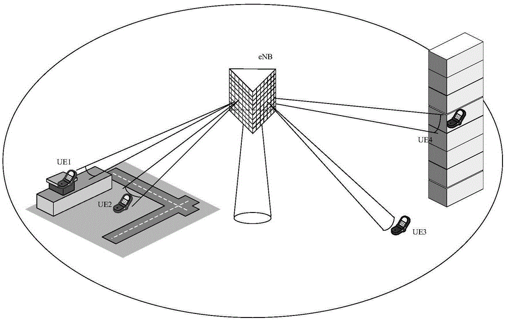
technical field [0001] The present disclosure relates to the technical field of wireless communication, and more particularly, to an apparatus and method in a wireless communication system for realizing hybrid three-dimensional beamforming based on large-scale antennas and fewer radio frequency links. Background technique [0002] With the continuous development of future mobile communications, 3D beamforming technology has received more and more attention. Massive antenna technology is considered to be one of the key technologies for the next generation of mobile communications (5G). figure 1 A scenario example of a massive-antenna multi-user-multiple-input multiple-output (MU-MIMO) system is shown, in which one base station and multiple user equipments are set up in a cell, and the base station is equipped with a massive antenna to serve the multiple user equipments Provide services. The spatial resolution of the system is improved due to the large-scale antennas used in...

Claims


Application Information

Patent Timeline
Patent Type & Authority Applications(China)
IPC IPC(8): H04W16/28
CPCH04W16/28G01S3/043G01S3/74H04B7/086H04W52/02G01S3/02H04B7/0897H04W64/00
Inventor 吴亮张在琛秦伟微郑黎丽党建吕本舜陈晋辉
Owner SONY CORP
Why Eureka
Try Eureka