
Optical fiber-digital synchronous interface system based on FPGA

A technology of synchronous interface and optical fiber, which is applied in the direction of time division multiplexing system, electrical components, multiplexing communication, etc., can solve the problems that it is difficult to flexibly meet the protection system, reduce the reliability of communication, etc., and achieve low hardware cost and maintenance convenient effect

Inactive Publication Date: 2017-05-10
成都瑞科电气有限公司
View PDF3 Cites 5 Cited by
  • Summary
  • Abstract
  • Description
  • Claims
  • Application Information

AI Technical Summary

Problems solved by technology

The traditional protection synchronous interface circuit design uses many related chip stacking circuits, such as SCC+separation components, SCC+CPLD+PLL or SCC+FPGA, which not only reduces the reliability of communication, but also makes it difficult to flexibly meet the requirements of the protection system

Method used


Image

  • Optical fiber-digital synchronous interface system based on FPGA
  • Optical fiber-digital synchronous interface system based on FPGA
  • Optical fiber-digital synchronous interface system based on FPGA

Examples


Embodiment Construction

[0026] The specific implementation manner of the present invention will be further described in detail below in conjunction with the accompanying drawings and specific examples.

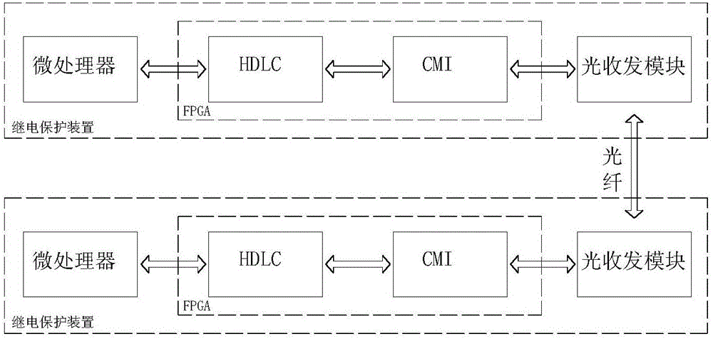
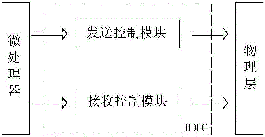
[0027] Such as Figure 1~2 As shown, a FPGA-based optical fiber digital synchronous interface system includes at least two relay protection devices and their interconnected optical fibers, and the relay protection devices include microprocessors, FPGA controllers and optical signal conversion Optical transceiver module, described FPGA controller comprises HDLC frame protocol transceiver and the physical layer optical fiber communication line that adopts CMI code, described HDLC frame protocol transceiver is made up of sending control module and receiving control module, microprocessor communicates with by bus mode The HDLC communication connection in the FPGA controller, the HDLC is connected to the CMI and then connected to the optical transceiver module.

[0028] After the serial HDLC frame is ass...


PUM


Abstract

The invention discloses an optical fiber-digital synchronous interface system based on FPGA. The system comprises a microprocessor, an FPGA controller and an optical transceiver module used for converting photoelectric signals, the FPGA controller comprises an HDLC frame protocol transceiver and a physical layer optical fiber communication line using CMI codes, the HDLC frame protocol transceiver is composed of a sending control module and a receiving control module, the microprocessor is in communication connection with the HDLC in the FPGA controller in a bus mode, and the HDLC communicates with the CMI and is connected with the optical transceiver module. The microprocessor of the system reads data in the FPGA through a read-write bus, an HDLC protocol and a CMI encoding and decoding function are realized by the FPGA, the traditional way of implementing the HDLC protocol by using SCC hardware can be omitted, the data in an opposite side relay protection device in optical fiber transmission are obtained, so optical fiber longitudinal differential protection can be realized, and the system has the advantages of low hardware cost, reliable communication, good flexibility and convenient maintenance.

Description

technical field [0001] The invention belongs to the field of electric power system relay protection, and in particular relates to an FPGA-based optical fiber digital synchronous interface system. Background technique [0002] With the increasing development of optical fiber digital communication technology and its gradual application in power systems, optical fiber longitudinal differential protection has gradually been widely used in transmission lines due to its simple principle and reliable performance. The popularization of optical fiber in power systems, As a result, optical fiber longitudinal differential protection is used more and more. Optical fiber differential protection requires that the data transmitted by optical fiber must be accurate, efficient, and real-time. Therefore, the design of optical fiber digital synchronous interface is very critical. The traditional protection synchronous interface circuit design uses many related chip stacking circuits, such as S...

Claims


Application Information

Patent Timeline
Patent Type & Authority Applications(China)
IPC IPC(8): H04J3/16
CPCH04J3/1611
Inventor 朱俊锋
Owner 成都瑞科电气有限公司
Learn More