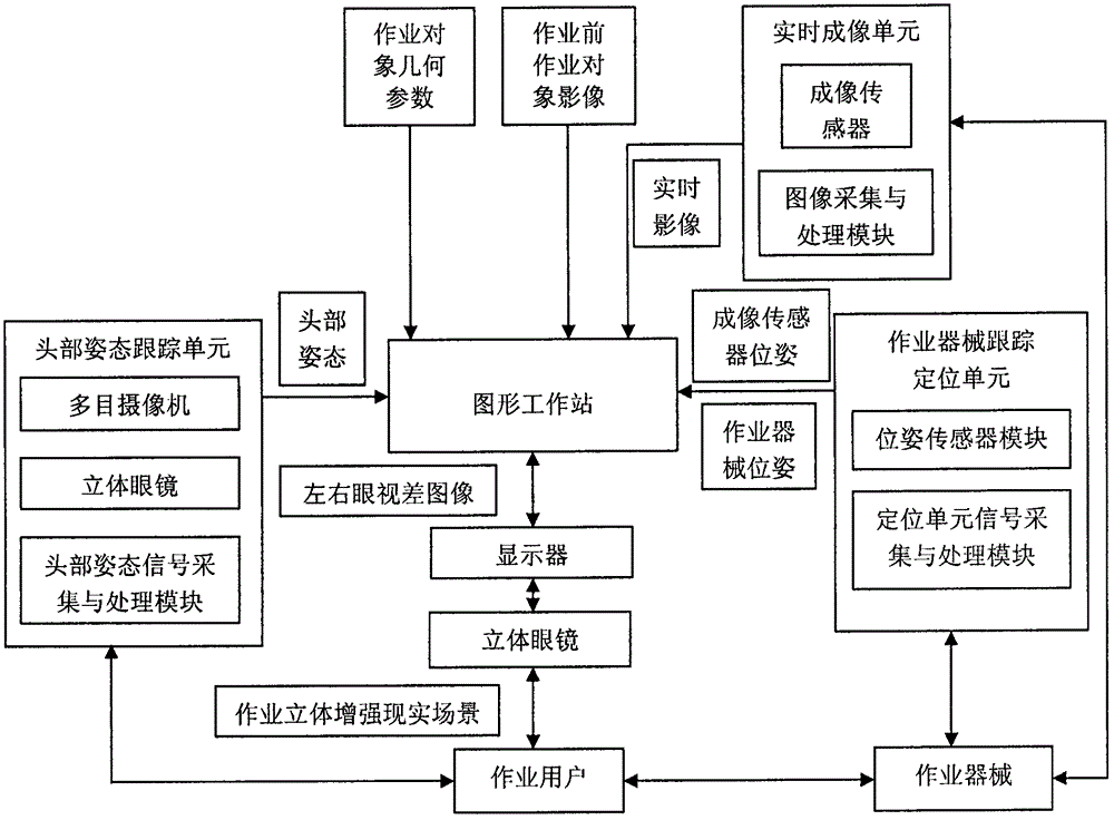
Adaptive dynamic stereoscopic augmented reality navigation system based on real-time tracking and multi-source information fusion
A technology of multi-source information fusion and real-time tracking, applied in image enhancement, input/output process of data processing, input/output of user/computer interaction, etc., can solve the problem of flexible and effective control of difficult-to-operate equipment, unfavorable precise and efficient operation , lack of human-computer interaction ability of depth of field information and other issues, to achieve the effect of improving cognitive ability, improving operation quality and efficiency
- Summary
- Abstract
- Description
- Claims
- Application Information
AI Technical Summary
Problems solved by technology
Method used
Image
Examples
Embodiment 1
[0015] Example 1: Minimally invasive spinal surgery
[0016] (1) Arrange multiple marker points around the patient’s lesion, and the number of marker points n is not less than 3; then perform tomographic imaging on the patient, and use the graphics workstation to process the tomographic images to obtain the coordinates of all marker points in the imaging system P= [P 1 , P 2 ,..., P n ] T As well as three-dimensional models of spine, blood vessels, nerves and other tissues, and plan the surgical path. The surgical path should avoid important tissues or organs as much as possible;
[0017] (2) Place the patient on the operating table, and use the work equipment tracking and positioning unit to obtain the coordinates of all the marked points arranged on the body of the loyal person in the positioning coordinate system P’=[P 1 ’, P 2 ’,..., P n ’] T ;
[0018] (3) According to the coordinates P and P'of the marking points arranged on the patient's body in the imaging system and the trac...
Embodiment 2
[0022] Example 2: Detection of engine defects
[0023] (1) According to the mechanical structure of the engine, establish the detection coordinate system and its three-dimensional model, and determine the coordinates of n corner points on the surface in the coordinate system P=[P 1 , P 2 ,..., P n ] T , N is not less than 3, and plan the defect detection path;
[0024] (2) Use the work equipment tracking and positioning unit to obtain the coordinates of the n corner points on the engine surface in the positioning coordinate system P’=[P 1 ’, P 2 ’,..., P n ’] T ;
[0025] (3) According to the coordinates P and P'in the detection coordinate system and the work equipment tracking and positioning coordinate system, use the above formula (1) to calculate the coordinate transformation to obtain the coordinate transformation matrix between the work equipment tracking and positioning coordinate system and the imaging coordinate system T 1 ;
[0026] (4) Use the graphics workstation to establ...
PUM
 Abstract
Description
Claims
Application Information
 - R&D
- Intellectual Property
- Life Sciences
- Materials
- Tech Scout
- Unparalleled Data Quality
- Higher Quality Content
- 60% Fewer Hallucinations
Browse by: Latest US Patents, China's latest patents, Technical Efficacy Thesaurus, Application Domain, Technology Topic, Popular Technical Reports.
© 2025 PatSnap. All rights reserved.Legal|Privacy policy|Modern Slavery Act Transparency Statement|Sitemap|About US| Contact US: help@patsnap.com

