
Transparent display

A transparent display and light guide plate technology, which is applied in the direction of instruments, optics, nonlinear optics, etc., can solve the problems of low contrast of transparent displays, poor image clarity, visual fatigue of human eyes, etc., and achieve good picture display effect and display effect Good, good permeability effect

Inactive Publication Date: 2017-05-10
UNIV OF ELECTRONIC SCI & TECH OF CHINA
View PDF11 Cites 11 Cited by
  • Summary
  • Abstract
  • Description
  • Claims
  • Application Information

AI Technical Summary

Problems solved by technology

[0005] However, the existing transparent displays represented by the above-mentioned patent documents have the disadvantage of low contrast, which is much lower than ordinary displays.
The reason is that since the transparent display has a certain degree of light penetration, the background on the back side of the transparent display will interfere with the image displayed on the transparent display, for example, when the pattern of the background on the back side overlaps with the image displayed on the transparent display or When presenting similar colors, it is easy to cause negative effects such as poor image clarity displayed on the transparent display and visual fatigue of the human eye.

Method used


Image

  • Transparent display

Examples


Embodiment Construction

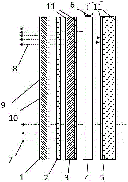
[0030] As the best implementation mode of the present invention, please refer to Fig. 1, the transparent display provided by the embodiment of the present invention includes normally white mode TFT-LCD (Thin Film Transistor Liquid Crystal Display) layer 1 and quantum conversion layer 2, PDLC (Polymer Dispersed Liquid Crystal) or PNLC (Polymer Network LiquidCrystal) layer 3, light guide plate layer 4, liquid crystal light changing layer 5.

[0031] As shown in the figure, the design of TFT-LCD layer 1 is a combined array substrate structure including front and rear polarizers, which has two states of imaging and transparency. The combined array substrate structure refers to the three-layer combined structure of 1, 9, and 10 in the figure, and the whole is called an array substrate. Among them, 9 is the structure of the front polarizer, which acts as a polarizer. 10 Rear polarizer, analyzer function. The substrate is a transparent glass substrate or plastic substrate, and the ...


PUM


Abstract

The invention discloses a transparent display, and relates to the technical field of electro-optic display. The transparent display comprises a TFT-LCD layer, a quantum conversion layer, a PDLC or PNLC layer, a light guide plate layer and a liquid crystal changing light layer which are arranged in sequence in a stacked mode, the TFT-LCD layer is a combined array substrate structure which contains a front polaroid and a rear polaroid; the quantum conversion layer is used for transforming an optical wavelength which is transmitted by light into light with another wavelength, which correspondingly illuminates an image under a TFT-LCD imaging pattern; the PDLC or PNLC layer is used for making penetrated light show a scattering state or a transparent state; the light guide plate layer is used for making LED strong light scatter and illuminate the image in the TFT-LCD layer; the liquid crystal changing light layer is of a layered shape structure which becomes mirror glass when electrified or becomes transparent glass when not electrified. Through the adoption of the transparent display, the contrast and the transmittance of the display are improved while the energy consumption is low and the service life is longer, compared with an ordinary scheme which relies on reflective light, the display effect is more excellent, the permeability is better, under the existing process technology, implementation is easier, and the cost is low.

Description

technical field [0001] The invention relates to the technical field of photoelectric display, in particular to a transparent display. Background technique [0002] With the development of display technology, liquid crystal display devices are widely used in a wide range of fields from small information terminals to transmissive large-scale projection equipment. More and more manufacturers have successively introduced transparent displays with see-through function. With transparent displays, the information displayed on the display can be seen when voltage is applied, and the information on the back of the display can be seen through the display when no voltage is applied. object. In addition to the original display function, the transparent display device can also have future display features such as providing information. Therefore, it has attracted market attention and may replace some markets that use displays in the future. It is expected that a large number of existing...

Claims


Application Information

Patent Timeline
IPC IPC(8): G02F1/1334G02F1/13357
CPCG02F1/1334G02F1/133615
Inventor 王继岷蒋向东高升旭曾一雄
Owner UNIV OF ELECTRONIC SCI & TECH OF CHINA
Learn More