A steel cage fixed mold

A reinforcement cage and mold technology, applied in construction, foundation structure engineering, sheet pile walls, etc., can solve the problems of reducing the image of civilized construction on site, affecting the quality of bored piles, and difficult control of the stability of reinforcement cages, etc., to achieve ingenious structure , Distributed force and wide application range

Active Publication Date: 2019-01-25
CHINA RAILWAY 24TH BUREAU GRP +1
View PDF5 Cites 0 Cited by
  • Summary
  • Abstract
  • Description
  • Claims
  • Application Information

AI Technical Summary

Problems solved by technology

[0002] In the construction of bridges and culverts or high-rise buildings, pile foundations usually use bored pile foundations. The construction of bored piles usually uses mud retaining wall punching or drilling, and then the reinforcement cage is lowered into the pile hole, and then the conduit is inserted for concrete pouring. Usually we use the drill The prefabricated steel structure of cast-in-place piles is called a reinforcement cage. During the construction process, the reinforcement cages need to be transported from the production site to the construction site of bored piles for temporary storage, but most of them are improperly stored during the storage process. It is round, and the processed finished product is easily deformed on the one hand, and on the other hand, it is difficult to control the stability of the steel cage when stacking. Usually, limit devices are required to be installed on both sides of the steel cage on a flat site to prevent the steel cage from being unstable. When stacked on top, the contact surface between the reinforcement cage and the ground is less, resulting in a large concentrated load, and the reinforcement cage is easy to deform, and the reinforcement cage is directly in contact with the ground and is covered with mud, which causes the surface of the reinforcement cage to corrode, affects the quality of the bored pile, and reduces the civilization of the site. construction image

Method used


Image

  • A steel cage fixed mold
  • A steel cage fixed mold
  • A steel cage fixed mold

Examples


Embodiment Construction

[0030] The present invention will be further explained below in conjunction with the accompanying drawings and specific embodiments. It should be understood that the following specific embodiments are only used to illustrate the present invention and are not intended to limit the scope of the present invention. It should be noted that the words "front", "rear", "left", "right", "upper" and "lower" used in the following description refer to the directions in the drawings, and the words "inner" and "outer ” refer to directions towards or away from the geometric center of a particular part, respectively.

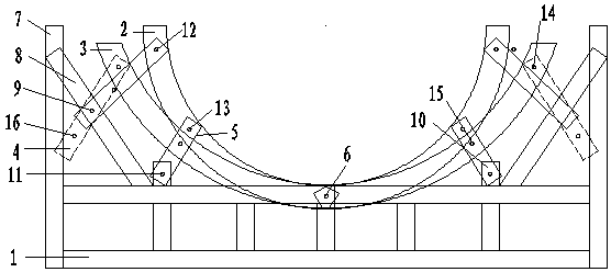
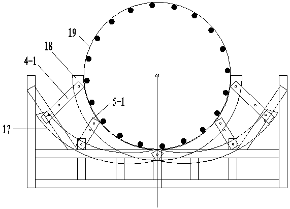
[0031] like figure 1 As shown, a kind of reinforcement cage fixed mold of the present invention comprises fixed frame 1, small movable hoop 2, large movable hoop 3, positioning steel sheet one 4, positioning steel sheet two 5 (positioning steel sheet one 4 is There are two types, namely the positioning steel sheet 1 4-1 on the small movable hoop and the locating steel sheet 1 ...


PUM


Abstract

The invention discloses a reinforcement cage fixing die. The reinforcement cage fixing die comprises a fixing frame, a large movable hoop, a small movable hoop, first positioning steel sheets and second positioning steel sheets; the large and small movable hoops are arranged on the upper edge of the fixing frame through locking blocks correspondingly and are movably connected to the fixing frame through the first positioning steel sheets and the second positioning steel sheets; and the first positioning steel sheets and the second positioning steel sheets are each provided with at least three seventh connecting holes. According to the reinforcement cage fixing die, the structure is ingenious, operation is convenient, and manufacturing is simple; the problem that reinforcement cages stacked on the flat ground are prone to being deformed can be solved, so that the quality of the reinforcement cages is ensured; in addition, the stability problem of the reinforcement cages can be solved, and the staff safety is ensured; the reinforcement cage fixing die can be used for fixing and storing the reinforcement cages with different diameters; rusting is avoided, the site construction image is improved, and the site standardized construction requirement is met; and the practicality is high, and the applicability is wide.

Description

technical field [0001] The invention belongs to the technical field of bored pile foundation construction in building construction, and in particular relates to a steel cage fixing mold. Background technique [0002] In the construction of bridges and culverts or high-rise buildings, pile foundations usually use bored pile foundations. The construction of bored piles usually uses mud retaining wall punching or drilling, and then the reinforcement cage is lowered into the pile hole, and then the conduit is inserted for concrete pouring. Usually we use the drill The prefabricated steel structure of cast-in-place piles is called a reinforcement cage. During the construction process, the reinforcement cages need to be transported from the production site to the construction site of bored piles for temporary storage, but most of them are improperly stored during the storage process. It is round, and the processed finished product is easily deformed on the one hand, and on the oth...

Claims


Application Information

Patent Timeline
Patent Type & Authority Patents(China)
IPC IPC(8): E02D5/34
CPCE02D5/34
Inventor 田继源金顺利
Owner CHINA RAILWAY 24TH BUREAU GRP
Why Eureka
Try Eureka