
Spring telescopic reed

A technology of telescopic reed and spring group, which is applied in the field of spring telescopic reed, can solve the problems of low efficiency, complex structure of telescopic reed, poor durability, etc., and achieve the effect of uniform and stable adjustment

Active Publication Date: 2018-10-12
常州意如筘座制造厂
View PDF7 Cites 0 Cited by
  • Summary
  • Abstract
  • Description
  • Claims
  • Application Information

AI Technical Summary

Problems solved by technology

[0004] However, the structure of this kind of telescopic reed is complex, and in order to realize that all the reed pins are always uniformly distributed during the telescopic process, high processing accuracy is required, the durability is poor, and the assembly process of the reed pins and the telescopic chain is cumbersome and inefficient.

Method used


Image

  • Spring telescopic reed
  • Spring telescopic reed
  • Spring telescopic reed

Examples


Embodiment 1

[0062] Example 1, such as figure 1 , 2 , 3, 4, 5, 6, 7, 8 and 9:

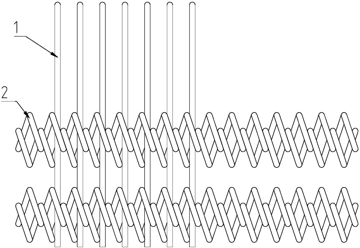
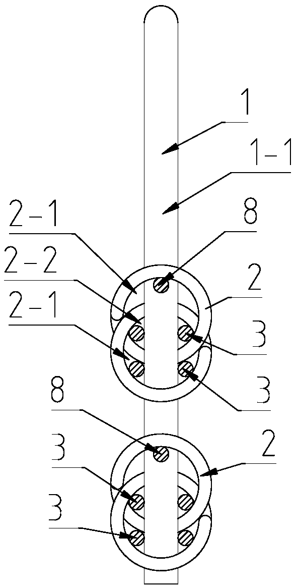
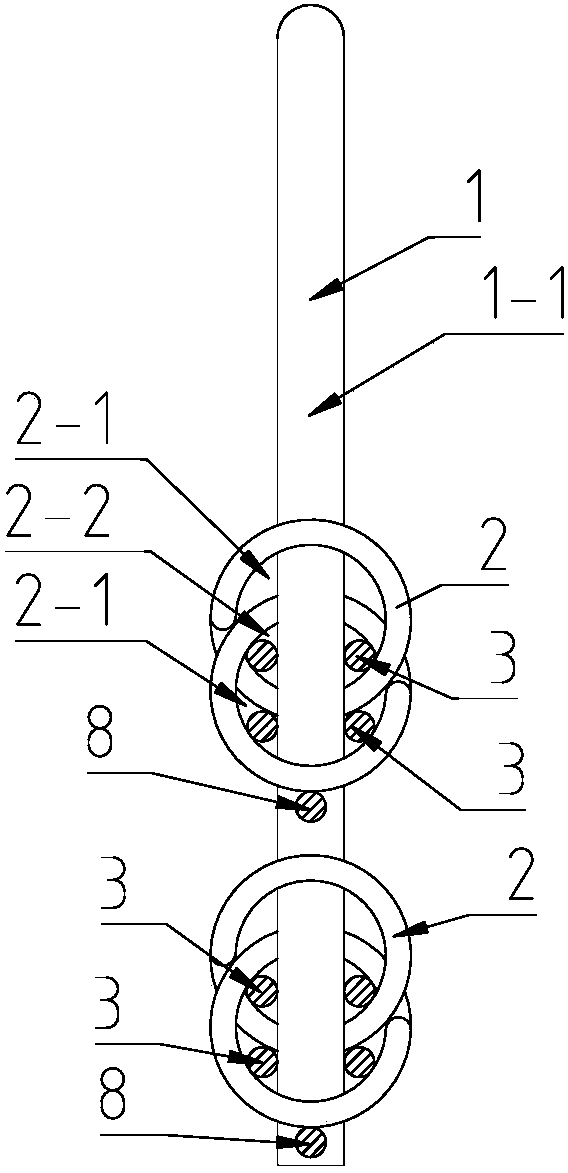
[0063] A spring telescopic reed, comprising a base 4, a telescopic drive mechanism, a spring group 2 and a reed needle row, wherein the reed needle 1 of the reed needle row is a straight flat reed needle and includes a needle bar part 1-1. The top surface of the base 4 has a needle groove 7 extending along the length direction of the base 4, and the telescopic drive mechanism and the spring group 2 are installed in the inner cavity of the base 4 in parallel along the length direction of the base 4. The reed needles of the reed needle row 1 are all positioned by the way that the needle bar part 1-1 penetrates into its supporting two or more coils of the spring group 2 arranged in a straight line up and down on the vertical plane, and passes through the base 4 from the needle groove 7.

[0064] The two adjacent coil springs in each spring group 2 are fitted and connected by interlocking each other's spring coil...

Embodiment 2

[0081] Example 2, such as Figure 10 , 11 and 12 as shown:

[0082] This embodiment 2 compares with embodiment 1, and difference point is: reed needle 1 comprises needle bar part 1-1 and beam part 1-2, has socket 1-2-1 on beam part 1-2, needle bar part 1-1 through the socket 1-2-1 through the crossbeam part 1-2, the reed needle 1 passes through the needle bar part 1-1 and the crossbeam part 1-2 respectively into the spring set 2, or the reed needle 1 only passes through the crossbeam part 1-2 thread into spring group 2.

Embodiment 3

[0083] Example 3, such as Figure 13 Shown:

[0084] This embodiment 3 is compared with embodiment 1, and the difference is: the reed needle 1 comprises a needle bar part 1-1 and a side arm part 1-3 extended from one side or both sides of the needle bar part 1-1, and the reed Either the needle 1 penetrates the spring set 2 via the needle shank part 1-1 and the side arm part 1-3 respectively, or the reed needle 1 penetrates the spring set 2 only via the side arm part 1-3.


PUM


Abstract

The invention relates to a spring expansion reed which comprises a base, a telescopic driving mechanism, spring sets and more than one reed needle row, wherein reed needles in each reed needle row are positioned in a manner of penetrating into the matched spring set; the telescopic driving mechanism drives the spring set to elongate or reset; each spring set drives the reed needles to move in the telescopic process so as to adjust the needle distance between two reed needles; two adjacent spiral springs in each spring set are in embedded connection in a manner of fastening the spring rings one by one; a supporting rod penetrates into the spring set; and a reed needle part penetrating into the spring set is positioned at a middle position of the spring ring. The spring expansion reed disclosed by the invention has the beneficial effects that the reed needles are clamped by the spring sets, so that the distance between the reed needles can be uniformly adjusted due to stretching and retraction of the springs. Meanwhile, due to the spring rods, the spring sets can be always kept in a relatively stable state in the whole telescopic adjusting process, all the reed needles have an equal clamping force and equal distance change, and the breadth of a plurality of counts of yarns can be uniformly and stably adjusted.

Description

technical field [0001] The invention relates to a spring telescopic reed. Background technique [0002] The telescopic reed is a yarn-separating part used in the textile field, and the existing telescopic reed is assembled together by a reed needle, a telescopic chain and a base. The telescopic chain applies the principle of angle change of the parallelogram. A hole is punched in the center and two ends of the fixed-length steel strip, and the upper and lower centers of the two steel strips are combined and riveted into one group, and the two ends of each group of steel strips are connected and riveted together. , forming a scalable working width. [0003] When the user uses the telescopic reed, first configure the required reed pins, install the reed pins piece by piece on the expansion chain of the expansion reed, the expansion chain is riveted with a card seat with a bayonet, and put the reed pins into the card In the bayonet of the seat and locked by screws. Weaving w...

Claims


Application Information

Patent Timeline
Patent Type & Authority Patents(China)
IPC IPC(8): D02H13/18
CPCD02H13/18
Inventor 沈全松
Owner 常州意如筘座制造厂
Learn More