
Automobile hub clamping fixture with automatic centering function

An automobile hub and automatic centering technology, applied in the direction of clamping, positioning devices, manufacturing tools, etc., can solve the problems of rising product failure rate, sluggish work efficiency, poor positioning accuracy, etc., to improve positioning and clamping accuracy, Improve work efficiency and improve the effect of using range

Inactive Publication Date: 2017-05-10
太仓市夏米粒信息技术有限公司
View PDF10 Cites 11 Cited by
  • Summary
  • Abstract
  • Description
  • Claims
  • Application Information

AI Technical Summary

Problems solved by technology

Therefore, when the automobile hub is running at high speed in its working state, in order to ensure the safety of the running car, there are high requirements for the strength and roundness of the wheel hub, otherwise there will be great safety hazards, and automobile driving accidents will occur.
[0003] Therefore, in the process of processing automobile wheels, tightening tooling is one of the necessary auxiliary tools for processing automobile wheels. To achieve accurate clamping, positioning and pressing is a necessary condition to ensure the roundness of automobile wheels and an important factor in wheel processing; , the traditional tightening tooling and positioning fixtures are mostly manually positioned and clamped, which not only causes sluggish work efficiency, but also poor positioning accuracy, resulting in an increase in the failure rate of products
At the same time, most of the existing fixtures are fixed and cannot be rotated, which is inconvenient to use and has poor stability; and the versatility is poor. For products of different specifications and sizes, different positioning fixtures need to be used, which causes In addition, the labor cost is high, and the later recycling process is troublesome and costly, which is not conducive to sustainable production

Method used


Image

  • Automobile hub clamping fixture with automatic centering function
  • Automobile hub clamping fixture with automatic centering function
  • Automobile hub clamping fixture with automatic centering function

Examples


Embodiment

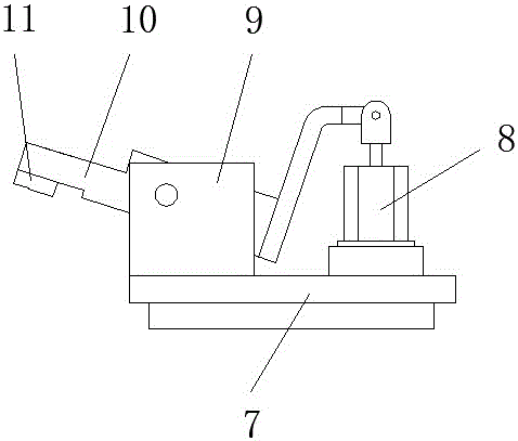
[0020] A kind of automobile hub clamping tool with automatic centering function described in the present invention, such as figure 1 , figure 2 As shown, it includes: a body 1 and a rotary table 2 arranged above the body 1; the body 1 is provided with a PLC control unit and an electric control unit that drives the rotary table 2 to rotate; the center of the rotary table 2 A pneumatic expansion shaft 3 is fixed; the pneumatic expansion shaft 3 is provided with pneumatic pressure blocks 4 uniformly distributed in the circumferential direction; the upper surface of the rotary table 2 is provided with positioning grooves 5 uniformly distributed in the radial direction; the positioning grooves 5 is provided with pressing module 6, such as image 3 As shown, the compression module 6 includes: a bottom plate 7 and a compression cylinder 8 and a bracket 9 arranged on the bottom plate 7; the compression cylinder 8 and the bracket 9 are aligned and arranged side by side; the bracket 9...


PUM


Abstract

The invention patent discloses an automobile hub clamping fixture with an automatic centering function, and belongs to the technical field of clamping fixtures. The automobile hub clamping fixture comprises a machine body and a rotary worktable arranged above the machine body; a PLC (Programmable Logic Controller) control unit and an electric control unit for driving the rotary worktable to rotate are arranged in the machine body; a pneumatic expansion shaft is fixedly arranged at the center of the rotary worktable; circumferentially uniformly distributed pneumatic blocks are arranged on the pneumatic expansion shaft; radially uniformly distributed positioning slots are arranged on the upper surface of the rotary worktable; a pressing module is arranged on the positioning slot; and the pneumatic expansion shaft and the pressing module are both connected with the PLC control unit. The automobile hub clamping fixture disclosed by the invention is simple in structure, reasonable in design, strong in university, and wide in applicable range. The automatic centering positioning can be realized, the processing efficiency of the product is greatly improved, the processing period is shortened, and the processing cost is saved.

Description

technical field [0001] The invention relates to the technical field of tooling for processing auto parts, in particular to an automotive hub clamping tool with an automatic centering function. Background technique [0002] The wheel hub is also called the rim, the wheel, and the tire bell. It is a barrel-shaped, center-mounted metal part that supports the tire on the inner profile of the tire. The wheel hub is an important driving part of the car, which bears most of the load generated during the driving process of the car. Therefore, the structure of the wheel hub affects the performance of the car to a large extent. Therefore, when the working state of the automobile hub is running at high speed, in order to ensure the safety of the running car, there are high requirements for the strength and roundness of the wheel hub, otherwise there will be great safety hazards and automobile driving accidents. [0003] Therefore, in the process of processing automobile wheels, tighte...

Claims


Application Information

Patent Timeline
IPC IPC(8): B23Q3/08
CPCB23Q3/08
Inventor 程嘉义
Owner 太仓市夏米粒信息技术有限公司
Learn More