
Design Method of Center of Gravity Dispersion Moment Balance Ball Mill

A design method and ball mill technology, applied in grain processing, etc., can solve the problems of high energy consumption of gravity resistance torque, friction resistance torque, etc., and achieve the effects of good strength structure, reduced energy consumption, and good energy saving effect

Active Publication Date: 2018-10-23
罗锦源 +1
View PDF6 Cites 0 Cited by
  • Summary
  • Abstract
  • Description
  • Claims
  • Application Information

AI Technical Summary

Problems solved by technology

[0011] In order to solve the problem of high energy consumption of gravity resistance torque and friction resistance torque of existing ball mills, a rolling friction instead of sliding friction is provided to reduce system resistance, and a gravity balance structure on both sides of the slewing support point is used to reduce energy consumption. Design Method of Center of Gravity Dispersion Moment Balance Ball Mill

Method used


Image

  • Design Method of Center of Gravity Dispersion Moment Balance Ball Mill
  • Design Method of Center of Gravity Dispersion Moment Balance Ball Mill
  • Design Method of Center of Gravity Dispersion Moment Balance Ball Mill

Examples


Embodiment 1

[0045] A. Change the single cylinder of the ball mill to a multi-cylinder structure to eliminate the resistance moment formed by the gravity of the processed material;

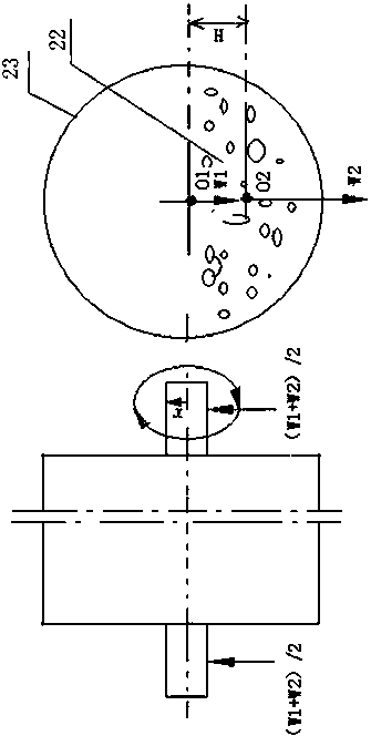
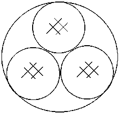
[0046] In this embodiment, the single cylinder of the ball mill is changed to three cylinders, and the force state during operation will change, such as figure 2 As shown, the single tube is changed to three small tubes fixed equilaterally, and the working state is the same as that of the single tube, and the central axis is also used to rotate. If the total weight of the ball mill barrel is W1, the total weight of the processed material is W2, and the weight of the material in each barrel is W2 / 3, the resistance torque that causes the ball mill to rotate at this time is mainly formed by the friction force generated by the total gravity and the shaft diameter. The resistance torque (W1+W2) μr; and the resistance torque generated by the weight of the materials in the three cylinders, at this time, because the mate...

Embodiment 2

[0049] Example 2 Energy-saving structure design of ball mill

[0050] The energy-saving structure of the ball mill has the following sections:

[0051] Energy-saving structure design scheme of cement ball mill, cement dryer, ceramic ball mill and other equipment

[0052] Intermittent ball mills used in ceramic factories are mostly center-rotating, and their working processes include three processes: feeding, rotary grinding, and discharging; ball mills and dryers used in cement factories are mostly supported by rollers, driven by peripherals, and barrels. It is in a rolling and rotating way with the idler. The barrel structure of this equipment can be designed into the following sections. The multi-tube structure has the following sections:

[0053] 1) Combine multiple (three or more) small diameter cylinders

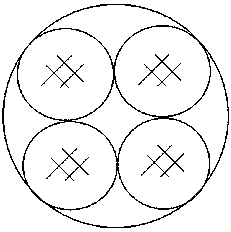
[0054] see Figure 7-9 , Replace the single-tube structure with three or more small cylinders of the same size. The principle of the center of gravity of each cylinder can be ...

Embodiment 3

[0061] When the intermittent ceramic ball mill adopts a torque balance structure, a drive device for loading and unloading should be added.

[0062] For the ball mill, when the center of gravity distributed torque balance structure is adopted, the working driving mode of the cylinder body is the same as the working driving mode of the traditional single cylinder, but for the intermittent ceramic ball mill, a set of upper and lower This is because the balanced ball mill has a multi-space structure. Each space must have an upper and lower material opening. Therefore, during the loading and unloading process, each upper and lower material opening should be positioned and fixed. The inlet and outlet of the The opening and closing of the inlet and outlet and the feeding process are carried out at the top, and the discharging process is carried out at the bottom to prevent the rotation of the cylinder due to the deviation of the center of gravity during the loading and unloading process...


PUM


Abstract

The invention discloses a design method of a gravity center scattering and moment balancing type ball mill. The gravity center scattering and moment balancing type ball mill comprises a driving motor. The design method is characterized by improving structures comprising a cylinder structure, a material inlet, a material outlet structure and a liner plate structure according to the categories of ball mills and a balance type design principle, and comprises the specific steps: changing a single cylinder of the ball mill into a multi-cylinder structure, and removing a resistance moment formed by the gravity of a processed material; combining multiple small-diameter cylinders, replacing a single-cylinder structure with multiple same-size small cylinder structures, and forming whole balance by utilizing the gravity action of each cylinder; equationally designing the single cylinder inito a multi-space structure; equationally dividing by using a big-small two-cylinder structure; adding a backstop in the material inlet of the ball mill in continuous feeding; adding a separating net in a boundary position of the front part and the rear part of the cylinder. The cylinder structure designed by the design method enables that the gravity resistance moment generated by the processed material in each equational area space to be zero and only a friction resistance moment exists; a balance type ball mill or a dryer is enabled to have a energy-saving effect; and better running balance is obtained.

Description

Technical field [0001] The invention relates to a design method of a ball mill, in particular to a design method of a center-of-gravity distributed moment balance ball mill. Background technique [0002] The principles of continuous ball mills and dryers used in the cement industry and intermittent ceramic ball mills used in the ceramics industry are all horizontal cylindrical structures. The cylindrical body is a single-tube structure and is supported by rollers at the bottom or center. The shaft is supported, and the cylinder body adopts the rotating form of rotary motion at the same time to achieve its working process. When working, the main power generated by the motor mainly overcomes two resistances. One is to overcome the resistance torque generated by the gravity of the processed material during the rotation of the cylinder, and the other is to overcome the weight of the equipment and the weight of the processed material and simultaneously drive the traction. The frictio...

Claims


Application Information

Patent Timeline
Patent Type & Authority Patents(China)
IPC IPC(8): B02C17/10B02C17/18B02C23/02B02C17/24
CPCB02C17/10B02C17/18B02C17/183B02C17/24
Inventor 冷更新张雨新冷鑫磊
Owner 罗锦源
Learn More