Eureka AIR delivers breakthrough ideas for toughest innovation challenges, trusted by R&D personnel around the world.

Building block robot cube sliding block mould assembly

A robot and cube technology, applied in the field of building block robots, can solve problems affecting the appearance and function of products, product defects, and the overall effect of building block robots, and achieve the effects of improving appearance, quality, and stability

Pending Publication Date: 2017-05-03
SHANGHAI XPARTNER ROBOTICS
View PDF0 Cites 0 Cited by
  • Summary
  • Abstract
  • Description
  • Claims
  • Application Information

AI Technical Summary

Problems solved by technology

[0005] However, for the above solution, although the problem of mold release is solved, some features of the product need to be removed, resulting in defects in the product, seriously affecting the appearance and function of the product, and thus affecting the overall effect of the building block robot

Method used


Image

  • Building block robot cube sliding block mould assembly
  • Building block robot cube sliding block mould assembly
  • Building block robot cube sliding block mould assembly

Examples


Embodiment Construction

[0024] image 3 It is a three-dimensional structural schematic diagram of a building block robot cube slider mold assembly according to a preferred embodiment of the present invention. Figure 4 It is a top view structural schematic diagram of a cube slider mold assembly of a building block robot according to a preferred embodiment of the present invention. Figure 5 It is a schematic cross-sectional structure cut along the line A-A of the cube slider mold assembly of the building block robot according to the preferred embodiment of the present invention.

[0025] Such as image 3 , Figure 4 , Figure 5 As shown, the building block robot cube slider mold assembly according to the preferred embodiment of the present invention includes: a first slider 20 , a second slider 30 , a first front mold insert 40 and a second front mold insert 50 .

[0026] Wherein, the first slide block 20 and the second slide block 30 are arranged oppositely, and the building block robot cube 100...


PUM


Abstract

The invention discloses a building block robot cube sliding block mould assembly. The building block robot cube sliding block mould assembly comprises a first sliding block, a second sliding block, a first front mould insert and a second front mould insert, wherein the first sliding block and the second sliding block face each other; a building block robot cube processed by the building block robot cube sliding block mould assembly is arranged between the first sliding block and the second sliding block; inverted buckles are arranged on the sides, facing towards the first sliding block and the second sliding block, of the building block robot cube correspondingly; furthermore, a first inverted buckle structure, which cooperates with the inverted buckle on the side, facing towards the first sliding block, of the building block robot cube is arranged at the bottom of the side, facing towards the building block robot cube, of the first front mould insert, and a second inverted buckle structure, which cooperates with the inverted buckle on the side, facing towards the second sliding block, of the building block robot cube is arranged at the bottom of the side, facing towards the building block robot cube, of the second front mould insert.

Description

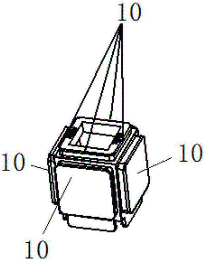
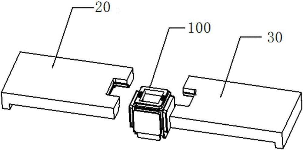
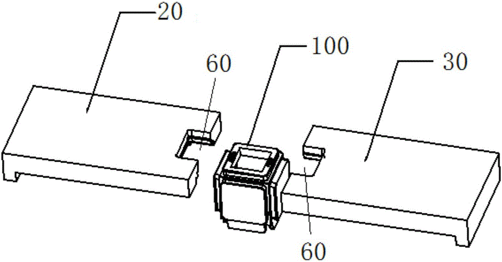
technical field [0001] The invention relates to the field of building block robots, in particular to a building block robot cube slider mold assembly. Background technique [0002] The building block robot cube is a splicing product, so it is used for assembly on all sides, resulting in the setting of undercuts on all sides. figure 1 is a schematic diagram of a building block robot cube. Such as figure 1 As shown, the four sides of the cube of the building block robot are provided with undercuts 10. [0003] However, this structure with undercuts all around affects the mold manufacturing, and the product needs to be modified to complete the smooth release of the product. specifically, figure 2 is a schematic diagram of a slider mold assembly according to the prior art. Such as figure 2 As shown, the building block robot cube 100 is arranged between the first slider 20 and the second slider 30 facing each other, because the building block robot cube 100 is facing the ...

Claims


Application Information

Patent Timeline
Patent Type & Authority Applications(China)
IPC IPC(8): B29C33/44B29L31/52
CPCB29C33/44B29L2031/5209
Inventor 恽为民孙军庞作伟
Owner SHANGHAI XPARTNER ROBOTICS
Why Eureka
Eureka Blog
Learn More