
RF emission method and circuit

A radio frequency transmission and circuit technology, applied in the field of radio frequency transmission, can solve the problems of affecting user experience, GSM calls cannot be dialed out normally, and affecting

Active Publication Date: 2017-04-26
TCL COMM (NINGBO) CO LTD
View PDF5 Cites 2 Cited by
  • Summary
  • Abstract
  • Description
  • Claims
  • Application Information

AI Technical Summary

Problems solved by technology

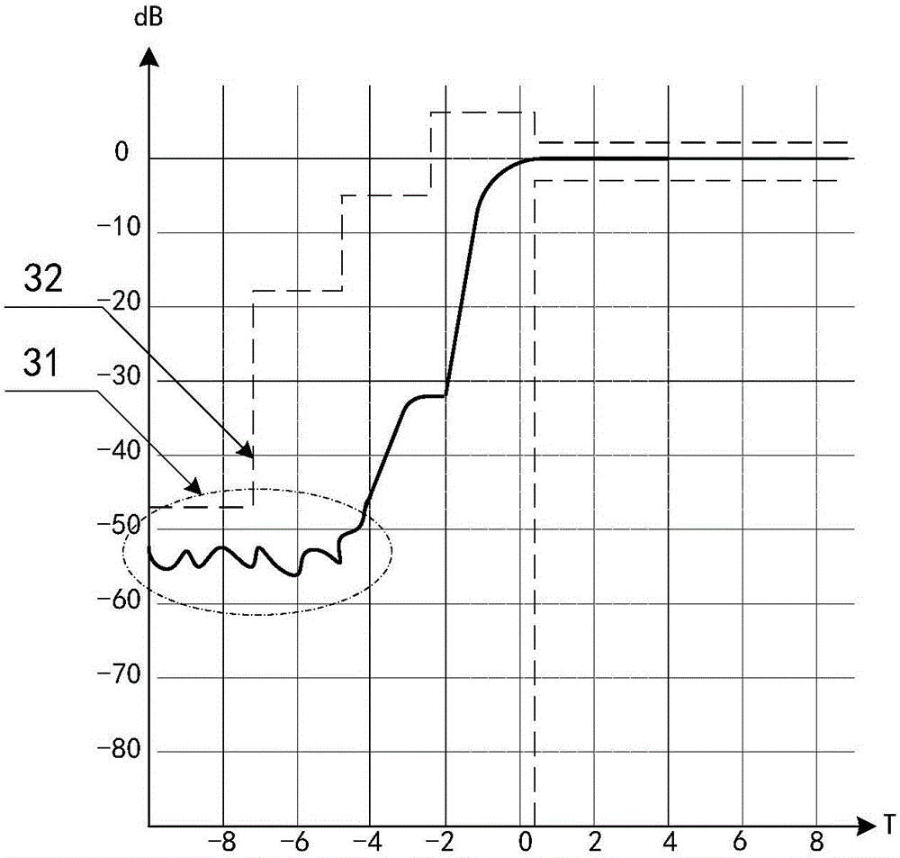
If the PvT exceeds the standard, it may affect other RF indicators, such as switching spectrum, modulation spectrum, phase error, etc., and may even directly cause GSM calls to fail to dial out normally, seriously affecting user experience

Method used


Image

  • RF emission method and circuit
  • RF emission method and circuit
  • RF emission method and circuit

Examples


Embodiment Construction

[0022] The present invention will be described in detail below in conjunction with the accompanying drawings and embodiments.

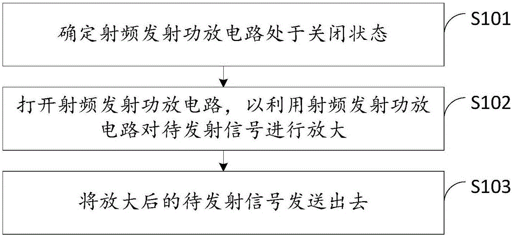
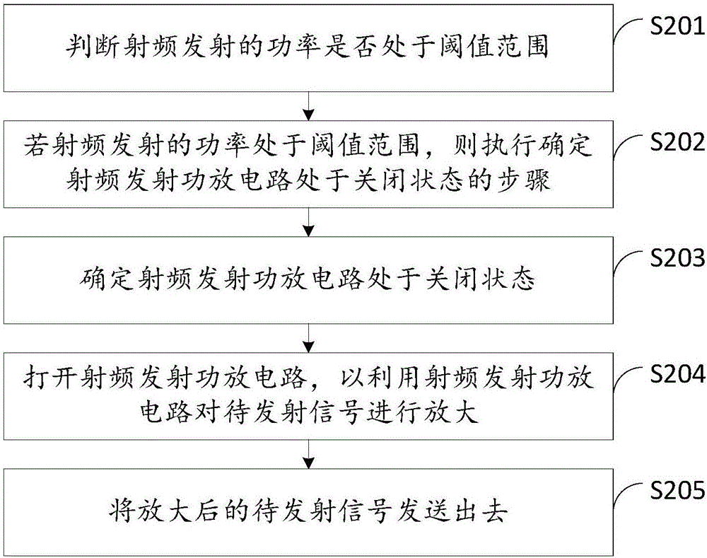
[0023] see figure 1 , figure 1 It is a schematic flow chart of an embodiment of the radio frequency transmission method of the present invention. It should be noted that if there are substantially the same results, the method of the present invention does not figure 1 The flow sequence shown is limited. Such as figure 1 As shown, the method includes the following steps:

[0024] S101: Determine that the radio frequency transmitting power amplifier circuit is in a closed state.

[0025] GSM is a digital mobile phone network standard developed by Europe. Its development purpose is to allow all parts of the world to use a common mobile phone network standard, so that users can use a mobile phone to travel around the world. The GSM system includes several frequency bands such as GSM900: 900MHz, GSM1800: 1800MHz and GSM1900: 1900MHz.

[0026] The GS...


PUM


Abstract

The invention discloses an RF emission method and circuit. The method comprise that an RF emission power amplification circuit is determined to be in an OFF state; the RF emission power amplification circuit is started to amplify a signal to be emitted; and the amplified signal to be emitted is emitted. Thus, ground noise can be reduced, and the problem that GSM PvT exceeds the standard is solved to certain extent.

Description

technical field [0001] The invention relates to the field of radio frequency modulation, in particular to a method and circuit for radio frequency transmission. Background technique [0002] The 3GPP (3rd Generation Partnership Project, 3rd Generation Partnership Project) standard requires that the GSM (Global System for Mobile Communication, Global System for Mobile Communication) PvT (Power versus Time, power time template) spectrum must meet specific requirements at each power level. Spectrum frame. If the PvT exceeds the standard, it may affect other RF indicators, such as switching spectrum, modulation spectrum, phase error, etc., and may even directly cause GSM calls to fail to dial out normally, seriously affecting user experience. Experience and practice have shown that PVT exceeding the standard mostly occurs at low power levels, especially at GSM high frequencies (GSM1800 and GSM1900) and the lowest power level, basically because the PvT noise floor is too high. ...

Claims


Application Information

Patent Timeline
Patent Type & Authority Applications(China)
IPC IPC(8): H04B1/04
CPCH04B1/04H04B1/0475H04B2001/0408
Inventor 张生胡志强
Owner TCL COMM (NINGBO) CO LTD
Learn More