
A high-efficiency high-rate lithium battery structure

A high-rate, lithium-ion battery technology, applied in structural parts, secondary batteries, battery pack components, etc., can solve problems such as increasing the discharge rate of lithium batteries, limiting the discharge rate of lithium batteries, and affecting the conductivity of lithium batteries. Simple and direct structure, good sealing and insulation, and the effect of reducing resistance and heat generation

Active Publication Date: 2019-06-21
ZHEJIANG GEELY HOLDING (GROUP) CO LTD
View PDF1 Cites 0 Cited by
  • Summary
  • Abstract
  • Description
  • Claims
  • Application Information

AI Technical Summary

Problems solved by technology

[0005] The present invention mainly solves the problems in the prior art that the tabs of the general lithium battery conduct electric energy through the welding pole, the welding process is difficult, the solder joints affect the conduction efficiency of the lithium battery, and the discharge rate of the lithium battery is limited, and it provides a tab that does not require welding. , reduce the production process, production time, production cost of high-efficiency high-rate lithium battery structure
In the present invention, the electrode ear is designed to be integrated, and there is no need to use poles to weld and connect the electrode ear at the lower part of the cover and the external terminal of the cover, which solves the problem of the existing lithium battery welding process bottleneck at these two places, and increases Improve the discharge rate of the lithium battery, reduce the resistance and heat caused by the welding point during high current discharge

Method used


Image

  • A high-efficiency high-rate lithium battery structure
  • A high-efficiency high-rate lithium battery structure
  • A high-efficiency high-rate lithium battery structure

Examples


Embodiment

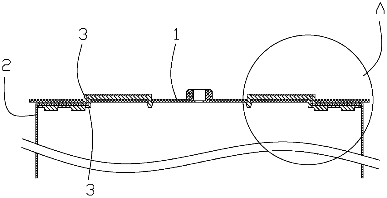
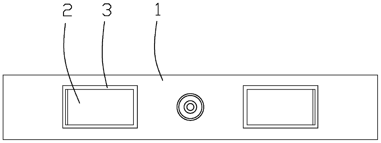
[0019] In this embodiment, a high-efficiency high-rate lithium battery structure, such as figure 1 As shown, the lithium battery includes a cover 1, and an electrode ear 2 is arranged under the cover, and the front end part 4 of the electrode ear passes through the cover and is located on the surface of the cover. The electrode lugs include copper lugs and aluminum lugs. The two lugs are respectively arranged on both sides of the safety valve. They are connected to the cover and the insulating layer in the same structure. In this embodiment, The copper tab and the aluminum tab are collectively referred to as the tab.

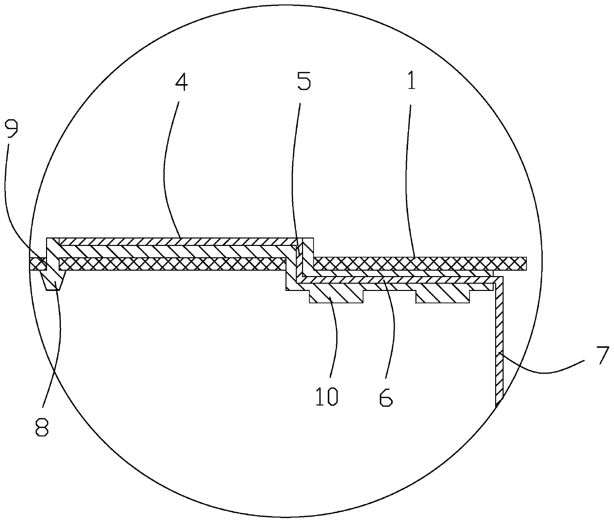
[0020] The electrode ear is in the form of a sheet, and the electrode ear includes a front part 4 and a rear part 6. The front part and the rear part are connected by a connecting part 5. The front part, the connecting part and the rear part form a ladder shape for the electrode ear Structure, the rear end of the electrode ear is extended downward to form an ex...


PUM


Abstract

The invention relates to a high-efficiency and high-rate lithium battery structure. It solves the problems that the general lithium battery tab conducts electric energy through the welding pole, the welding process is difficult, the welding point affects the conduction efficiency of the lithium battery, and the discharge rate of the lithium battery is limited. The battery structure includes a cover, and an electrode-taking ear is arranged under the cover. The front-end part of the electrode-taking ear passes through the cover and is located on the surface of the cover. The insulating layer is wrapped on the electrode-taking ear. External terminals are formed on the upper surface of the insulating layer on the cover. The advantage of the invention is that the electrode ear is taken in an integrated design, which solves the problem of the process bottleneck of the existing lithium battery welding at these two places, increases the discharge rate of the lithium battery, and reduces the resistance and resistance caused by the welding point during high current discharge. Fever condition. The tab insulation layer directly wraps the electrode tab, which produces good sealing and insulation with the battery cover. The overall structure is simple, and the manufacturing process, manufacturing time and material cost of the lithium battery are reduced.

Description

technical field [0001] The invention relates to the technical field of batteries, in particular to a high-efficiency and high-rate lithium battery structure that does not require welding of tabs and reduces manufacturing processes, manufacturing time, and manufacturing costs. Background technique [0002] With the continuous improvement of society's energy-saving and environmental protection requirements, electric vehicles have become the development direction of modern automobile industry technology. The current power source of electric vehicles is mainly based on the way of storing electric energy. The technology of storing electric energy with the background of current science and technology is being updated day by day. Among them, lithium battery technology has become the main direction of electric vehicle storing electric energy due to its excellent performance. [0003] At present, the existing lithium battery power-taking method in the market is basically that the bat...

Claims


Application Information

Patent Timeline
Patent Type & Authority Patents(China)
IPC IPC(8): H01M2/26H01M2/34H01M10/0525H01M10/058
CPCH01M10/0525H01M10/058H01M50/531H01M50/572Y02E60/10Y02P70/50
Inventor 张宝利周晓兵杨建国
Owner ZHEJIANG GEELY HOLDING (GROUP) CO LTD
Learn More