
Broadband gas-liquid two-phase spring pulsation damper

A pulsation damper and gas-liquid technology, applied in the direction of pipes/pipe joints/fittings, mechanical equipment, pipe components, etc., can solve the problems of pipeline vibration, difficulty in bearing high pressure, high replacement cost, etc., and achieve simple structure of the device and withstand pressure High, light weight effect

Inactive Publication Date: 2017-04-26
北京华德创业环保设备有限公司
View PDF8 Cites 4 Cited by
  • Summary
  • Abstract
  • Description
  • Claims
  • Application Information

AI Technical Summary

Problems solved by technology

The fluid pulsation generated during the operation of the volumetric conveying equipment will not only cause the instantaneous flow imbalance of the fluid, but also cause the vibration and wear of the conveying pipeline, and then cause the failure and damage of the pipeline and the pipeline connection.
In order to solve this problem, some devices such as diaphragm buffer tanks, hose buffers and piston buffers have been applied in engineering practice in this technical field. Defects such as short life, high replacement cost, and difficulty in withstanding high pressure; especially the above-mentioned diaphragm buffer tanks, hose buffers, and piston buffers absorb pulsation energy through the deformation of filling compressible gas, so they are only suitable for pulsation Applications with frequency less than 7Hz, because if the frequency is too high, the diaphragm, air bag or piston will not respond in time, and the effect of eliminating pulsation will not be achieved

Method used


Image

  • Broadband gas-liquid two-phase spring pulsation damper
  • Broadband gas-liquid two-phase spring pulsation damper
  • Broadband gas-liquid two-phase spring pulsation damper

Examples


Embodiment Construction

[0025] In order to make the object, technical solution and advantages of the present invention clearer, the present invention will be further described in detail below in conjunction with specific embodiments and drawings. In the drawings and / or descriptions in the specification, the same or similar parts all use the same figure numbers. Implementations that are not shown or described in the figures are forms known to those of ordinary skill in the technical field.

[0026] The following description of the embodiments is for those skilled in the art to understand and apply the present invention. It is obvious that those skilled in the art can easily modify these embodiments and apply the general principles described here to other embodiments without having to pay creative efforts. Therefore, the present invention is not limited to the embodiments herein. All modifications and improvements made by those skilled in the art according to the technical principles described in the...


PUM


Abstract

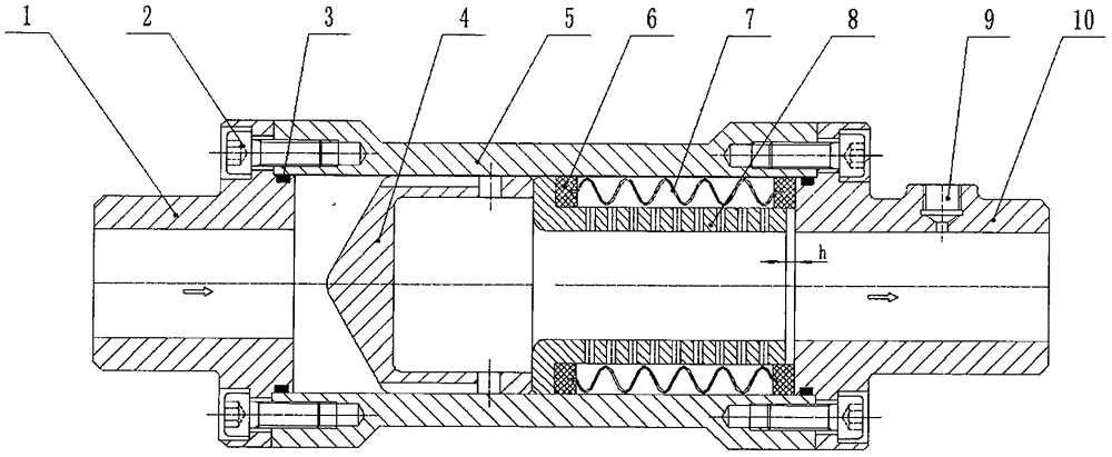
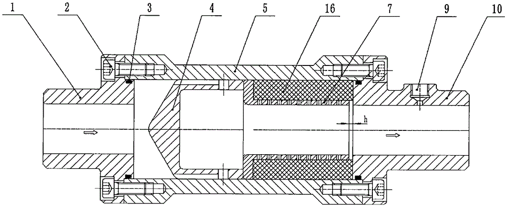
The invention discloses a broadband gas-liquid two-phase spring pulsation damper which comprises parts including an inlet end communication body, a sealing ring, a buffer cap, a body, a rubber spring or corrugated pipe spring, a flow passing net barrel, an outlet end communication body and the like. According to pulsatile fluid flowing through the inlet end of the broadband gas-liquid two-phase spring pulsation damper, fluid peak value kinetic energy is transmitted to the rubber spring or corrugated pipe spring in the body through end flanges of the buffer cap and the flow passing net barrel, and the rubber spring or corrugated pipe spring generates elastic deformation to absorb pulsation kinetic energy; and when a fluid peak value comes, the rubber spring or corrugated pipe spring releases stored energy and recover deformation. Through circulated reciprocation of the above process, fluid pressure pulsation is restrained. The broadband gas-liquid two-phase spring pulsation damper is suitable for fluid pulsation eliminating of liquid flow and gas flow within the 0-80Hz pulsation frequency range. The broadband gas-liquid two-phase spring pulsation damper has the obvious effects of being simple in device structure, small in size, light and high in bearing pressure compared with a traditional damper, and the pulsation eliminating rate is 95% or above.

Description

technical field [0001] The invention belongs to the technical field of hydraulic and pneumatic fluids, and relates to a broadband gas-liquid two-phase spring pulsation damper including gas, liquid and gas-liquid two-phase fluid. Background technique [0002] A fluid conveying device that includes pistons, plungers, diaphragms, gears or blades and other working parts that reciprocate or rotate in the pump body is alternately inhaled by periodically changing the volume of a single or several working chambers in the pump body. And the displacement of fluid, the change in volume will cause the pulsation of the delivered fluid. The fluid pulsation generated when the volumetric conveying equipment is working will not only cause the instantaneous flow imbalance of the fluid, but also cause the vibration and wear of the conveying pipeline, which will cause the failure and damage of the pipeline and the pipeline connection. In order to solve this problem, some devices such as diaphr...

Claims


Application Information

Patent Timeline
IPC IPC(8): F16L55/05
CPCF16L55/05
Inventor 吴学民吴静轩
Owner 北京华德创业环保设备有限公司
Learn More