
Exhaust postprocessing device and method used for engine

An exhaust post-treatment and engine technology, which is applied to the electronic control of exhaust treatment devices, exhaust treatment, exhaust devices, etc., can solve problems such as fuel consumption deterioration, reduction of intake air after-treatment, and impact on engine power. To achieve the effect of reducing cooling

Inactive Publication Date: 2017-04-26
WEICHAI POWER CO LTD
View PDF6 Cites 4 Cited by
  • Summary
  • Abstract
  • Description
  • Claims
  • Application Information

AI Technical Summary

Problems solved by technology

With the upgrading of emission regulations, exhaust post-treatment has gradually become an indispensable part of the engine. However, since the exhaust post-treatment has certain requirements for temperature, in order to meet the emission results of the engine in normal operating conditions that meet the requirements of the regulations, usually It is necessary to increase the exhaust temperature (also called exhaust temperature) under lower load conditions during the calibration process, and the negative effect is to worsen fuel consumption
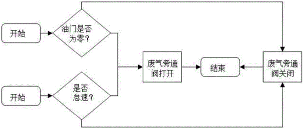
[0003] One way to reduce the demand for exhaust temperature is to reduce the cooling of the after-treatment components by the low-temperature exhaust gas under the condition of idling speed (with a small amount of fuel injection) and the throttle is zero. The usual method is to set an air intake throttle valve in the intake pipe. And under the working conditions of idling speed and zero throttle, the opening of the air intake throttle valve is reduced, thereby reducing the intake air volume and thus reducing the cooling of the aftertreatment, but this method is due to the valve response of the air intake throttle valve. It takes time. Correspondingly, it takes time to increase the speed of the supercharger, which often affects the subsequent acceleration, which in turn affects the dynamic performance of the engine.

Method used


Image

  • Exhaust postprocessing device and method used for engine
  • Exhaust postprocessing device and method used for engine

Examples


Embodiment Construction

[0022] Exemplary embodiments of the present disclosure will be described in more detail below with reference to the accompanying drawings. Although exemplary embodiments of the present disclosure are shown in the drawings, it should be understood that the present disclosure may be embodied in various forms and should not be limited by the embodiments set forth herein. Rather, these embodiments are provided for more thorough understanding of the present disclosure and to fully convey the scope of the present disclosure to those skilled in the art.

[0023] The following will refer to figure 1 and figure 2 An exhaust aftertreatment device for an engine and an exhaust aftertreatment method according to an embodiment of the present invention will be described.

[0024] Such as figure 1 As shown, the exhaust aftertreatment device for an engine according to the embodiment of the present invention includes: an aftertreatment component 10 for aftertreatment of engine exhaust, a by...


PUM


Abstract

The invention provides an exhaust postprocessing device and method used for an engine. The exhaust postprocessing device comprises a postprocessing part used for conducting postprocessing on exhaust of the engine and arranged in an exhaust pipeline, a bypass branch and a bypass valve, wherein an inlet and an outlet of the bypass branch communicate to the exhaust pipeline located at the inlet end and the outlet end of the postprocessing part correspondingly; and the bypass valve is arranged in the bypass branch and used for enabling exhausted gas from the engine to wholly or at least partially bypass the postprocessing part according to commands of an electronic control unit of the engine.

Description

technical field [0001] The invention relates to an exhaust aftertreatment technology, in particular to an exhaust aftertreatment device and an exhaust aftertreatment method for an engine. Background technique [0002] With the development of automobile technology, the requirements for automobile emission levels are getting higher and higher. In order to protect the environment and reduce automobile exhaust pollution, different countries have formulated different emission regulations or standards. With the upgrading of emission regulations, exhaust post-treatment has gradually become an indispensable part of the engine. However, since the exhaust post-treatment has certain requirements for temperature, in order to meet the emission results of the engine in normal operating conditions that meet the requirements of the regulations, usually It is necessary to increase the exhaust gas temperature (also called exhaust temperature) under lower load conditions during the calibration...

Claims


Application Information

Patent Timeline
Patent Type & Authority Applications(China)
IPC IPC(8): F01N13/00F01N9/00
CPCF01N9/00F01N13/00Y02T10/40
Inventor 李志杰刘静王作峰
Owner WEICHAI POWER CO LTD
Learn More