Gas lift reverse circulation negative pressure sand cleaning method and sand cleaning device
A technology of gas lift reverse circulation and sand cleaning, which is applied in earthwork drilling, wellbore/well components, construction, etc., which can solve the problems of pressure drop, leakage, and inability to carry sand out of the wellbore through sand settling in the wellbore, so as to improve the timeliness, Reduced operating costs and less risk of sand jams
- Summary
- Abstract
- Description
- Claims
- Application Information
AI Technical Summary
Problems solved by technology
Method used
Image
Examples
Embodiment 1
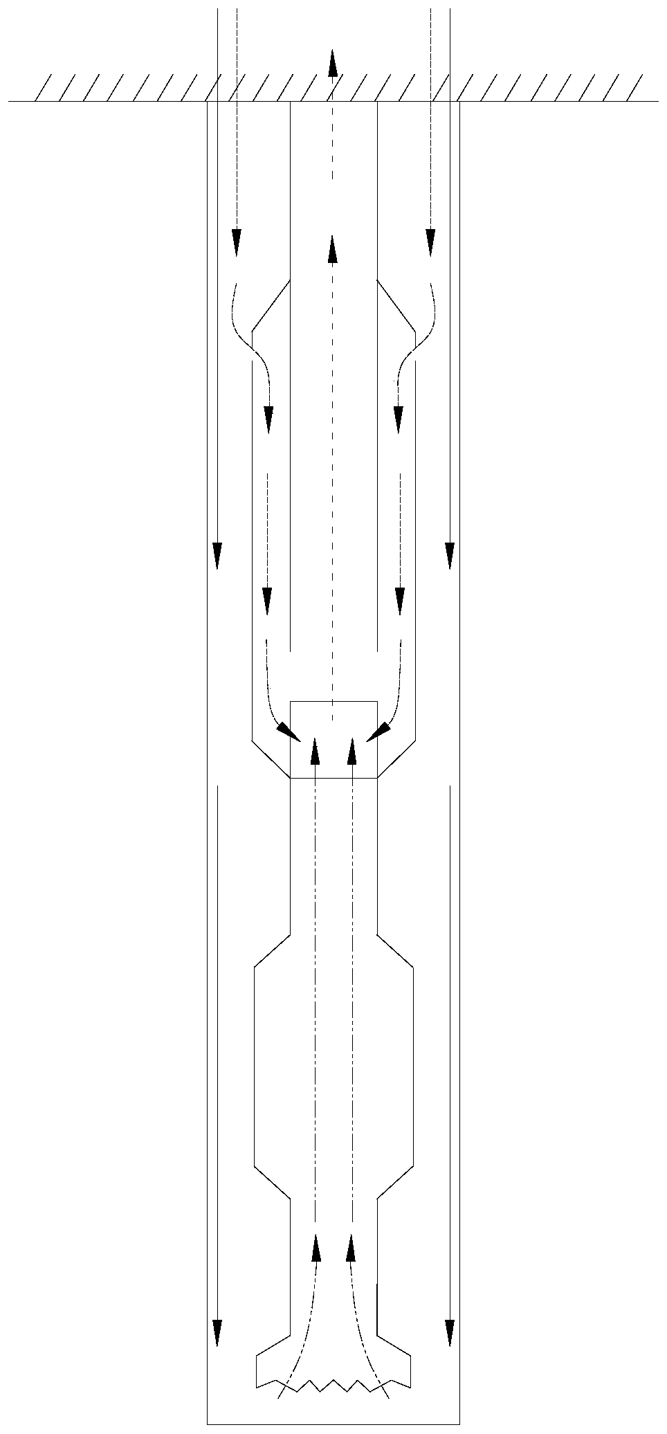
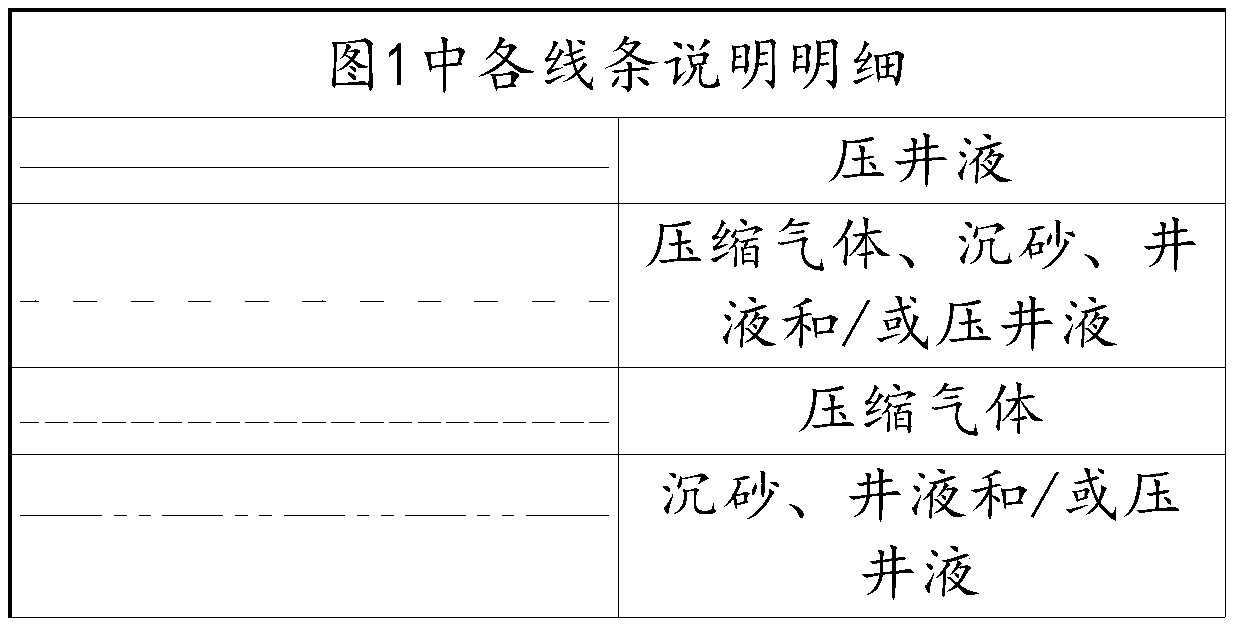
[0028] Such as figure 1 The present invention provides a gas-lift reverse cycle negative pressure sand cleaning method, which includes the following steps: injecting compressed gas into the sand cleaning device, the compressed gas expands in the sand cleaning device, and the inside of the sand cleaning device The pressure of the wellbore forms a negative pressure relative to the pressure in the wellbore. Under the action of negative pressure, the sand and well fluid in the wellbore enter the sand cleaning device and are discharged by gas lift in the sand cleaning device. Realize sand removal. With the above technical scheme, the bottom of the wellbore maintains negative pressure during the whole process of sand removal, which can effectively prevent sand from pouring into the formation and effectively protect the reservoir; there is no leakage during the sand removal process, no pollution to the formation, no need for flowback and resumption of production, and high efficiency ...
Embodiment 2
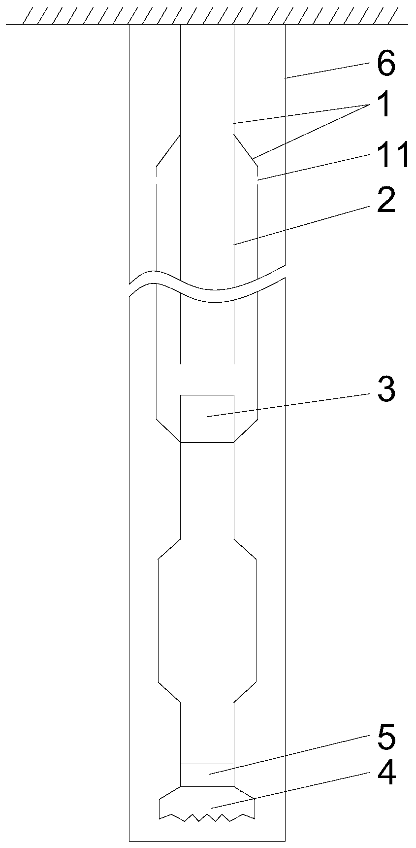
[0035] In order to realize the gas lift reverse circulation negative pressure sand cleaning method, such as figure 2As shown, the present invention also provides a gas-lift reverse cycle negative pressure sand cleaning device, the inside of the injection outer pipe 1 is sequentially provided with the injection inner pipe 2 and the gas-water mixer 3, and the injection inner pipe 2 The outer wall and the inner wall of the spraying outer tube 1 form an annular space, and the side wall of the spraying outer tube 1 is provided with a through hole 11, and the through hole 11 arranged on the side wall of the spraying outer tube 1 is preferably a supply gas And / or the through hole for the liquid to flow in one direction can be realized by installing a valve on the through hole. The through hole 11 is higher than the bottom of the spray inner tube 2, and the length of the spray inner tube 2 is less than The length of the spraying outer pipe 1, the top of the spraying inner pipe 2 is s...
PUM
 Abstract
Description
Claims
Application Information
 - R&D
- Intellectual Property
- Life Sciences
- Materials
- Tech Scout
- Unparalleled Data Quality
- Higher Quality Content
- 60% Fewer Hallucinations
Browse by: Latest US Patents, China's latest patents, Technical Efficacy Thesaurus, Application Domain, Technology Topic, Popular Technical Reports.
© 2025 PatSnap. All rights reserved.Legal|Privacy policy|Modern Slavery Act Transparency Statement|Sitemap|About US| Contact US: help@patsnap.com


