
Rod taking device for broken rod of thread connecting rod piece and construction method thereof

A technology of threaded connecting rods and construction methods, which is applied in the fields of drill pipes, earthwork drilling, sustainable buildings, etc., and can solve the problem that broken rods of threaded connecting rods cannot be taken out, so as to ensure convenience and effectiveness, and save maintenance costs , to ensure the effect of stability

Active Publication Date: 2017-04-26
BEIJING JANDC GEOTECHNICAL CONSTR LTD +1
View PDF6 Cites 2 Cited by
  • Summary
  • Abstract
  • Description
  • Claims
  • Application Information

AI Technical Summary

Problems solved by technology

[0003] The purpose of the present invention is to provide a threaded connecting rod broken rod removal device and its construction method, to solve the technical problem that the threaded connecting rod cannot be taken out when the structure breaks

Method used


Image

  • Rod taking device for broken rod of thread connecting rod piece and construction method thereof
  • Rod taking device for broken rod of thread connecting rod piece and construction method thereof
  • Rod taking device for broken rod of thread connecting rod piece and construction method thereof

Examples


Embodiment 1

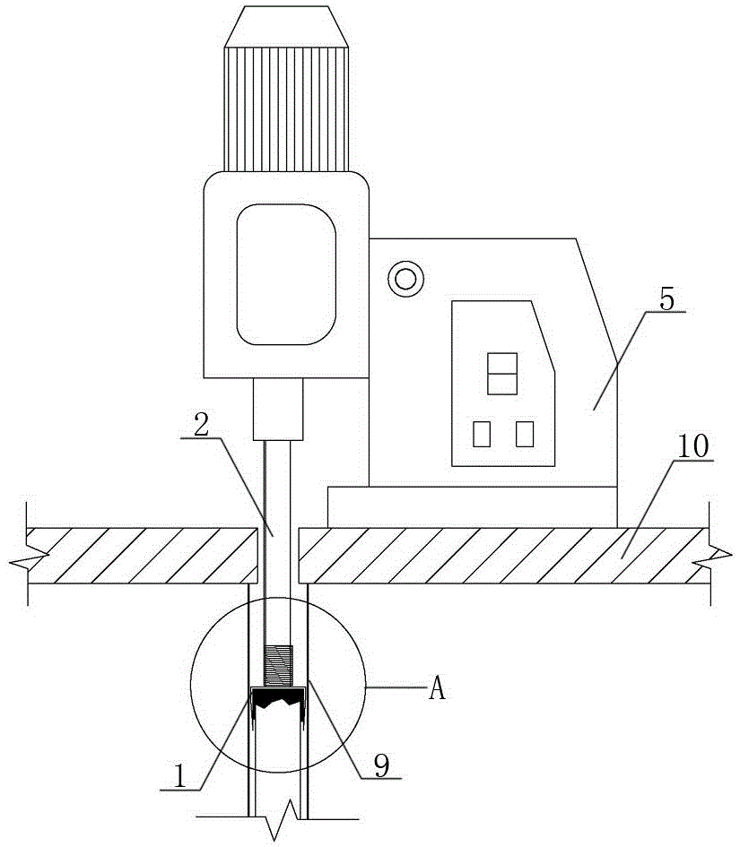
[0047] Embodiment one sees figure 1 As shown, this device for taking broken rods with threaded rods includes a drill base 5 and a drill rod 2 connected to the drill base 5, the end of the drill rod 2 is detachably connected with a connecting joint 1; the drill The rod 2 is formed by detachably connecting a group of rod joints 3 in sequence.

[0048] The drill rod 2 is a straight shank drill rod, and its end is connected with the drill base 5 through a straight shank clamp.

[0049] see image 3 As shown, the center of one end of the rod section 3 is provided with a threaded blind hole, and the center of the other end is correspondingly provided with a threaded joint, and the adjacent rod sections 3 are threaded; the length of the rod section 3 is 200mm, 300mm, 500mm And three or four specifications of 1000mm; the rod joint 3 is sleeved with an annular limiter 4; the limiter 4 is a bearing or a bushing, which is sleeved on the shaft of the rod joint 3 and passes through the r...

Embodiment 2

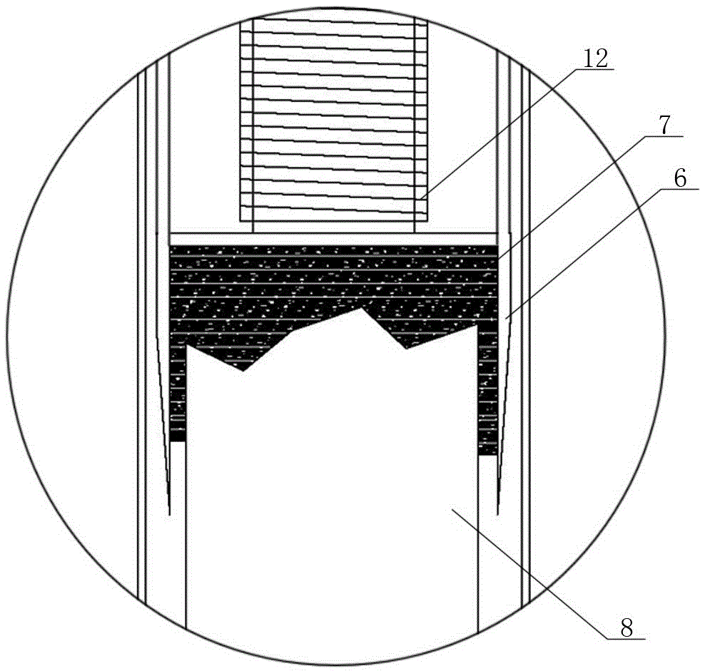
[0067] Embodiment two see Figure 4 As shown, the difference from the first embodiment is that one end of the rod joint 3 is welded or interference-fitted with a limit sleeve 11, and the other end is provided with an external thread, and the adjacent rod joints 3 are passed through a limit sleeve. The connection joint 1 includes a connection base and a sheath 6 vertically connected to the connection base; the upper end surface of the base is provided with a connection hole for use with the external thread of the end of the rod joint; the rod joint passes through a limit The outer diameter of the limiting sleeve is adapted to the diameter of the construction hole. One end of the limiting sleeve is welded to the rod joint 3 or the other end is threaded with the rod joint through interference fit to realize the adjacent rod joints. detachable connection.


PUM


Abstract

The invention provides a rod taking device for a broken rod of a thread connecting rod piece and a construction method thereof. The rod taking device comprises a drilling machine base and a drilling rod connected to the drilling machine base. A connecting connector is detachably connected to the end of the drilling rod, and the drilling rod is formed through ordinal and detachable connection of a set of rod sections. For prestress construction, when the rod piece is broken, the indwelled broken rod basically cannot be taken out due to the facts that the size of a construction hole of the thread connecting rod piece is small, the depth of the construction hole is more than three meters, and the diameter is less than 50 mm. According to the rod taking device for the broken rod of the thread connecting rod piece and the construction method thereof, the indwelled broken rod indwelled in the structure construction hole can be taken out, replacement of the thread connecting rod piece is achieved, construction hazards are eliminated, meanwhile a great deal of maintenance cost is reduced, and the economic value is improved.

Description

technical field [0001] The invention relates to the field of building construction, in particular to a construction device and a construction method for threaded rods. Background technique [0002] At present, the racks and towers of large or very large equipment, including wind generators, wind turbines, power line street lighting and signaling devices, bridge supports, commercial signs, highway signboards, ski lifts and other buildings are all constructed on site. Concrete foundation support, in order to ensure a more stable structure, often use threaded connection rods, such as prestressed anchor bolts, prestressed anchor rods, but in the specific construction process, due to some special circumstances or the quality of the rods, some rods The component breaks directly in the structure. Taking the wind turbine tower as an example, two circles of prestressed anchor bolts are arranged in a ring in the anchor cage ring foundation. The rods are located at the lower part of t...

Claims


Application Information

Patent Timeline
Patent Type & Authority Applications(China)
IPC IPC(8): E21B19/18
CPCY02B10/30E21B19/18
Inventor 石健季东波申宽育胡永柱关庆华李振作田伟辉崔振磊瓮文芳张钦喜马云龙马利鑫石岩
Owner BEIJING JANDC GEOTECHNICAL CONSTR LTD
Learn More