Mold carving machine
A technology of engraving machines and molds, applied in engraving, painting tools, processing models, etc., can solve the problems of simple positioning structure and huge turning mechanism, and achieve the effect of accurate and reliable positioning and exquisite design
Active Publication Date: 2017-04-26
DONGGUAN FALA CNC EQUIP
View PDF6 Cites 1 Cited by
- Summary
- Abstract
- Description
- Claims
- Application Information
AI Technical Summary
Problems solved by technology
Once the workpiece in the mold engraving machine needs to be turned over, it must be equipped with a turning mechanism that drives the workpiece to turn over. The existing turning mechanism of the mold engraving machine that needs to be turned over is relatively large, and the positioning structure is relatively simple.
Method used
View moreImage
Smart ImageViewing Examples

Examples
Embodiment 1
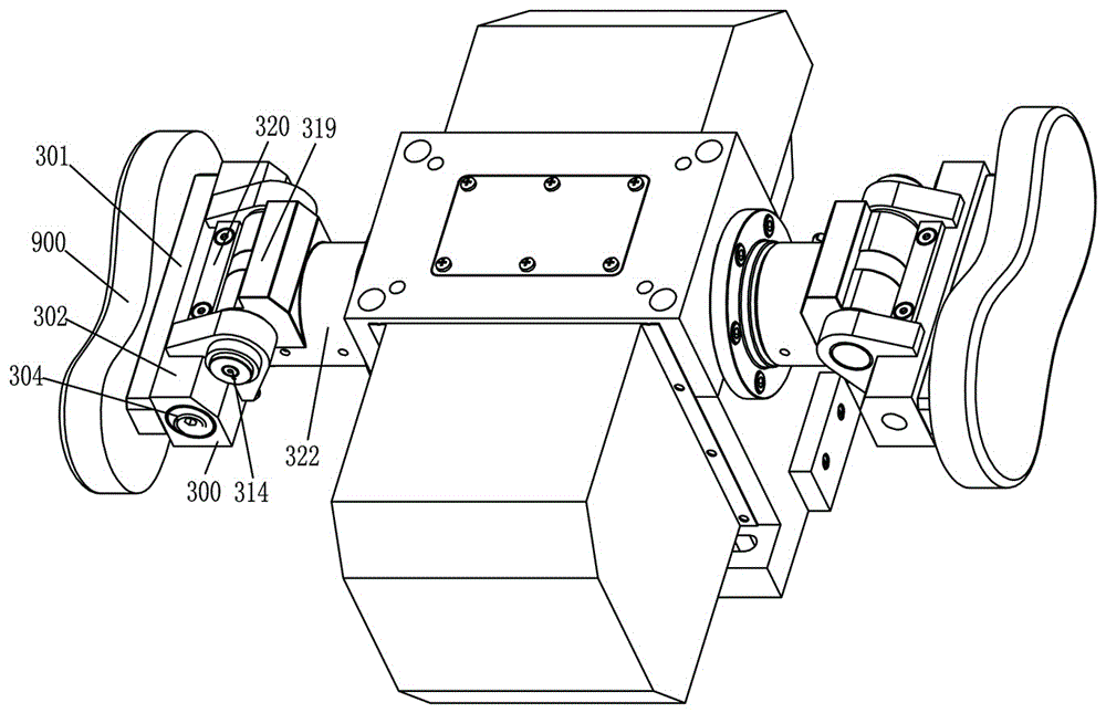
[0098] The difference between Embodiments 1, 2, and 3 lies in the positioning mechanism 300 and the rotating shaft 201 in the turning mechanism 200. The drawings in the specification mainly show the interior of Embodiment 1, but the traction mechanisms 100 of the three embodiments are all Therefore, it is sufficient to refer to the internal structure of Embodiment 1 completely.
Login to View More PUM
 Abstract
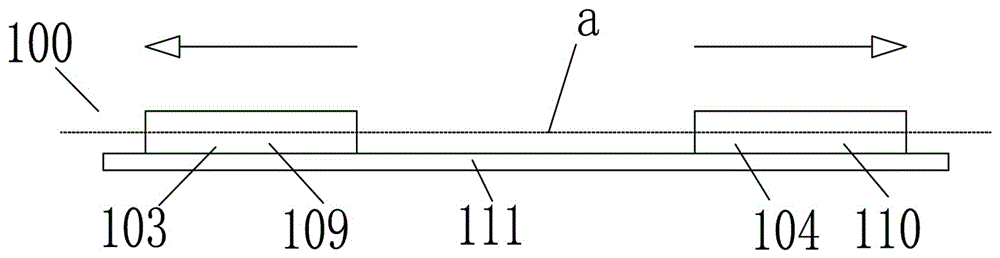
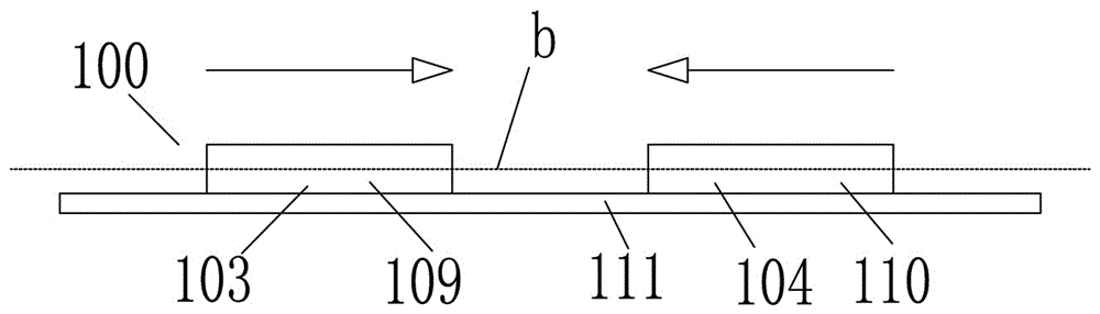
The invention discloses a mold carving machine. The mold carving machine has a traction mechanism, an overturning mechanism and a positioning mechanism; the traction mechanism has a first movable state, a second movable state and a static state; the overturning mechanism has a rotating shaft; the rotating shaft has an axial lead; the axial lead is a straight line; the rotating shaft is overturned with the axial lead as center; the rotating shaft has a rotating shaft limiting part and a rotating shaft following part; in the first movable state, the traction mechanism is separated from the rotating shaft limiting part; in the first movable state, the traction mechanism is linked with the rotating shaft following part; in the second movable state, the traction mechanism is separated from the rotating shaft limiting part; in the second movable state, the traction mechanism and the rotating shaft following part relatively move; in the static state, the traction mechanism is bonded with the rotating shaft limiting part; in the static state, the traction mechanism and the rotating shaft following part are both static; the positioning mechanism has a connecting plate, a base block and a locking pin; the base block has a base block locking cylinder; the locking pin and the connecting plate are fixedly assembled; the locking pin and the base block are assembled in a relative moving manner; the locking pin has a locking pin first inclined surface; the base block locking cylinder has a base block piston rod; and the base block piston rod has a base block piston rod inclined surface.
Description
technical field [0001] The invention relates to a mold engraving machine, and is especially suitable for an engraving machine that clamps workpieces and cooperates with turning them over. Background technique [0002] Mold engraving machine is widely used in various occasions where molds are used together. Once the workpiece in the mold engraving machine needs to be turned over, it must be equipped with a turning mechanism to drive the turning of the workpiece. The turning mechanism of the existing mold engraving machine that needs to be turned over is relatively large, and the positioning structure is relatively simple. Contents of the invention [0003] In order to overcome the above defects, the present invention provides a mold engraving machine with compact structure and reliable positioning structure. [0004] The mold engraving machine provided by the present invention has a traction mechanism, an overturning mechanism and a positioning mechanism. The traction mech...
Claims
Login to View More Application Information
Patent Timeline
 Patent Type & Authority Applications(China)
IPC IPC(8): B44B1/00B44B1/06
CPCB44B1/00B44B1/06B44B3/00B44B3/065B44B2700/12
Inventor 黄昌镜
Owner DONGGUAN FALA CNC EQUIP
Features
- R&D
- Intellectual Property
- Life Sciences
- Materials
- Tech Scout
- Unparalleled Data Quality
- Higher Quality Content
- 60% Fewer Hallucinations
Learn More Browse by: Latest US Patents, China's latest patents, Technical Efficacy Thesaurus, Application Domain, Technology Topic, Popular Technical Reports.
© 2025 PatSnap. All rights reserved.Legal|Privacy policy|Modern Slavery Act Transparency Statement|Sitemap|About US| Contact US: help@patsnap.com