A profile cutting device

A cutting device and profile technology, applied in the direction of manufacturing tools, grinding feed movement, grinding machine tool parts, etc., can solve the problems of affecting the cutting effect, prone to deflection, and low work efficiency, so as to improve production efficiency , stable positioning, avoiding the effect of deflection

Active Publication Date: 2020-05-22
嘉兴赛德家具股份有限公司
View PDF6 Cites 0 Cited by
  • Summary
  • Abstract
  • Description
  • Claims
  • Application Information

AI Technical Summary

Problems solved by technology

[0002] At present, plastic doors and windows are commonly used window structures in buildings. Plastic doors and windows are usually composed of profiles such as stiles and layering bars. Profile cutting machines are suitable for sawing various special-shaped metals such as aluminum, aluminum alloys, copper, copper alloys, non-metallic plastics, and carbon fibers. It is especially suitable for sawing aluminum doors and windows, photo frames, plastic steel materials, bakelite boards, aluminum extrusions, paper tubes and profiles. During the processing of building profiles, it is necessary to cut the profiles into different lengths and lengths according to the actual situation. The original cutting method is to mark on the profile according to the actual required length, and cut at the mark. This traditional application of the profile cutting machine has problems such as insufficient positioning of the profile, unstable positioning, etc., high labor intensity and low work efficiency. When cutting, it is prone to deflection, etc., which affects the cutting effect and is not conducive to production. For profiles that require inclined incisions, the profiles need to be removed from the fixture and reinstalled. The operation is cumbersome, so it is necessary to propose a profile cutting device

Method used


Image

  • A profile cutting device
  • A profile cutting device
  • A profile cutting device

Examples


Embodiment Construction

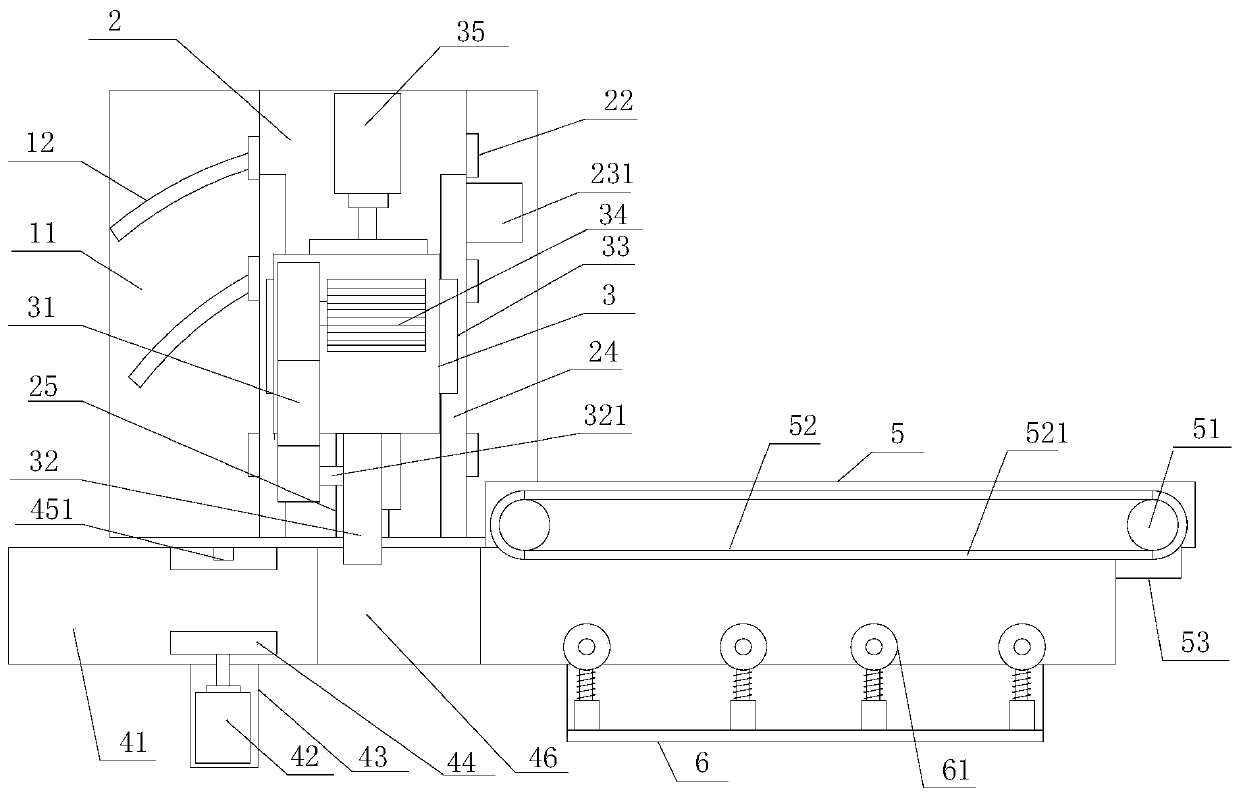
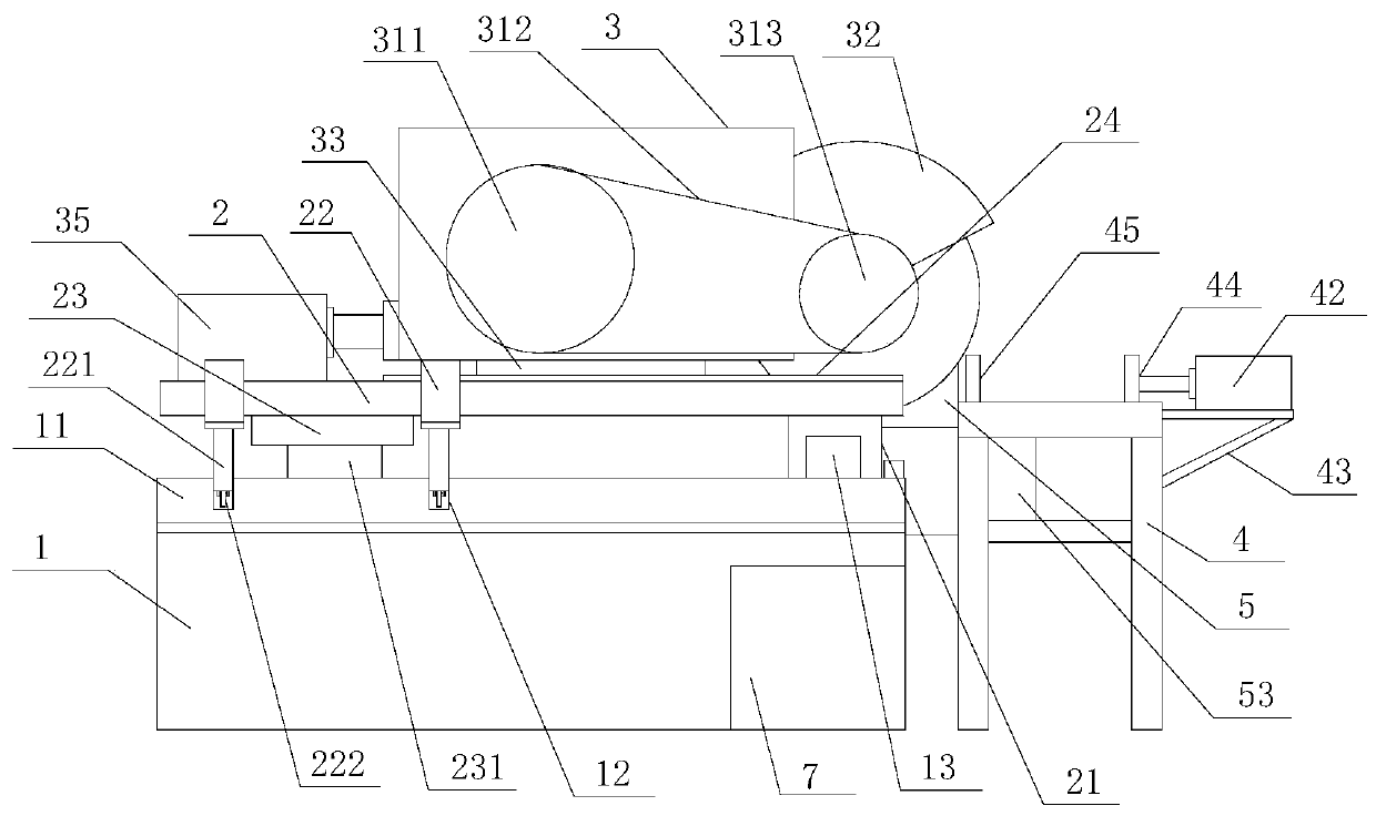
[0018] refer to Figure 1 to Figure 4 , a profile cutting device of the present invention includes a frame 1, an angle adjustment table 2, a cutting device 3, a feeding frame 4, a feeding device 5, a limit device 6 and a control system 7, and the frame 1 is provided with a mounting platform 11. One side of the mounting table 11 is provided with a supporting rotating shaft 13, and a supporting rotating seat 21 is provided under the angle adjusting table 2, and the supporting rotating seat 21 is matched with the supporting rotating shaft 13, and the angle adjusting table 2 There are several auxiliary walking frames 22 on the top, and several walking grooves 12 are opened on the installation platform 11. The auxiliary walking frames 22 cooperate with the walking grooves 12, and an adjustment drive mechanism 23 is installed under the angle adjustment platform 2. , the adjustment drive mechanism 23 drives the angle adjustment table 2 to rotate around the support shaft 13, the angle...


PUM


Abstract

The invention provides a section steel cutting device, which comprises a rack, an angle adjusting table, a cutting device, a feeding frame, a feeding device, a limiting device and a control system. A supporting rotary shaft is arranged on the rack; an adjustment drive mechanism is arranged under the angle adjusting table and drives the angle adjusting table to rotate around the supporting rotary shaft; the cutting device is arranged on the angle adjusting table; a transmission mechanism is arranged on the cutting device and drives a grinding wheel to rotate through a transmission shaft; the feeding frame is arranged in front of the cutting device; an auxiliary clamping cylinder is arranged on the feeding frame and is connected with the control system; a telescoping cylinder of the auxiliary clamping cylinder is connected with a movable clamping block; a conveyor belt is arranged on the feeding device; the limiting device is arranged on the opposite side of the conveyor belt; and a plurality of auxiliary drive wheels are arranged on the limiting device. The section steel cutting device is accurate in positioning, ensures a cutting effect, can be used for continuously cutting section steel automatically, and is beneficial to improving the production efficiency.

Description

【Technical field】 [0001] The invention relates to the technical field of profile processing equipment, in particular to a profile cutting device. 【Background technique】 [0002] At present, plastic doors and windows are commonly used window structures in buildings. Plastic doors and windows are usually composed of profiles such as stiles and layering bars. Profile cutting machines are suitable for sawing various special-shaped metals such as aluminum, aluminum alloys, copper, copper alloys, non-metallic plastics, and carbon fibers. It is especially suitable for sawing aluminum doors and windows, photo frames, plastic steel materials, bakelite boards, aluminum extrusions, paper tubes and profiles. During the processing of building profiles, it is necessary to cut the profiles into different lengths and lengths according to the actual situation. The original cutting method is to mark on the profile according to the actual required length, and cut at the mark. This traditional ...

Claims


Application Information

Patent Timeline
Patent Type & Authority Patents(China)
IPC IPC(8): B24B27/06B24B41/00B24B41/02
CPCB24B27/0683B24B41/005B24B41/02
Inventor 陈相忠
Owner 嘉兴赛德家具股份有限公司
Why Eureka
Try Eureka