
Cleaning brush idle shaft structure and usage method of cleaning equipment after cmp

A post-cleaning and cleaning brush technology, which is applied in the field of cleaning brush idler shaft structure, can solve the problems of poor wetting effect of cleaning brush, large concentricity deviation of idler shaft, poor bearing rigidity, etc., so as to improve rigidity, improve concentricity, The effect of ensuring airtightness

Active Publication Date: 2019-05-17
BEIJING SEMICORE PRECISION MICROELECTRONICS EQUIP CO LTD
View PDF5 Cites 0 Cited by
  • Summary
  • Abstract
  • Description
  • Claims
  • Application Information

AI Technical Summary

Problems solved by technology

[0004] The present invention provides a cleaning brush idler shaft structure of post-CMP cleaning equipment and its use method. It is necessary to solve the problem of insufficient fluidity of the water inlet mode of the cleaning brush idler shaft structure of the existing post-CMP cleaning equipment, poor bearing rigidity and no backlash removal treatment, and the idler shaft is concentric The technical problem that the degree deviation is large and the infiltration effect on the cleaning brush is not good

Method used


Image

  • Cleaning brush idle shaft structure and usage method of cleaning equipment after cmp
  • Cleaning brush idle shaft structure and usage method of cleaning equipment after cmp
  • Cleaning brush idle shaft structure and usage method of cleaning equipment after cmp

Examples


Embodiment Construction

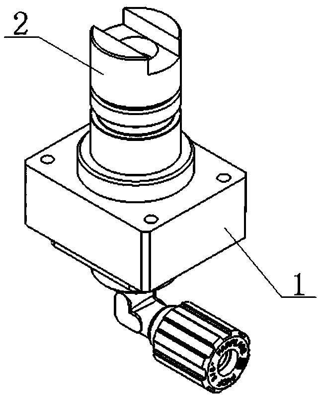
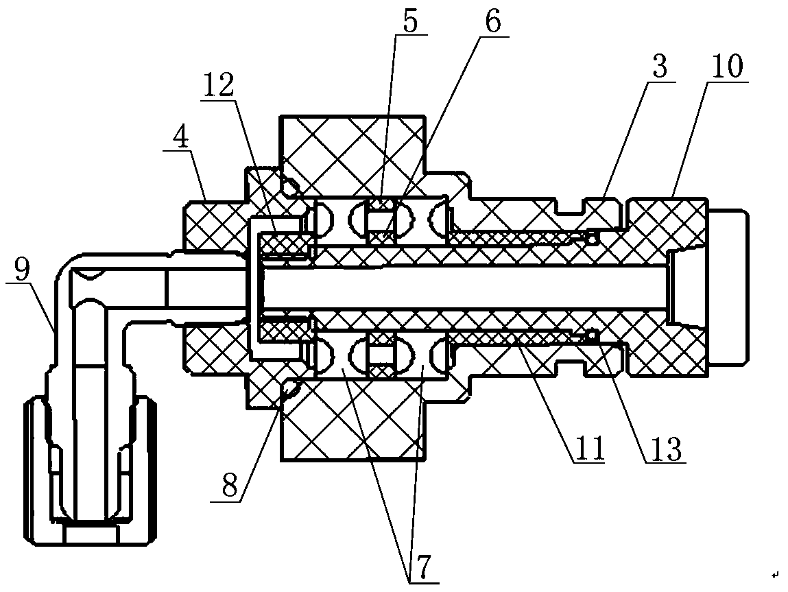
[0029] Examples see figure 1 , figure 2 As shown, the cleaning brush idle shaft structure of the post-CMP cleaning equipment includes a cavity unit 1 and an idle shaft unit 2 that is socketed with the cavity unit 1 .

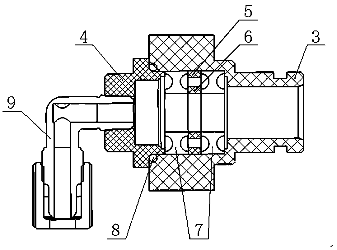
[0030] see image 3 As shown, the cavity unit 1 includes a cavity seat 3 , a combined bearing 7 , an outer spacer 5 , an inner spacer 6 , a gland 4 and a right-angle joint 9 . The combined bearing 7 is made of ceramic material, and the combined bearing 7 is pressed into the cavity seat 3 in a hole-axis positioning manner. The outer spacer 5 and the inner spacer 6 are between the bearings of the combined bearing 7 to eliminate backlash in the axial direction of the bearing. An O-ring 8 is provided between the front port of the gland 4 and the rear port of the cavity seat 3, and the O-ring 8 is tightly fitted and sealed. The right-angled joint 9 penetrates into the rear port of the gland 4 and is screwed tightly with the gland 4 for sealing.

[0031] see F...


PUM


Abstract

Provided are an idler shaft structure of a cleaning brush of CMP post-cleaning equipment and a use method of the idler shaft structure. The structure comprises a cavity unit and an idler shaft unit which is combined with the cavity unit in a muff coupling mode. The cavity unit comprises a cavity seat, a combined bearing, an outer spacer ring, an inner spacer ring, a gland and a right-angle joint. The idler shaft unit comprises an idler shaft, a Glyd ring, a spacer bushing and a lock nut. The idler shaft unit penetrates into the combined bearing of the cavity unit in a hole axis positioning mode, and the combined bearing is located between the lock nut and the spacer bushing of the idler shaft unit. The lock nut in the idler shaft unit and the gland in the cavity unit are matched with the inner spacer ring and the outer spacer ring between bearings so that axial clearance elimination of the combined bearing can be achieved. The cavity unit of the idler shaft structure can lead in pure water for soaking the cleaning brush and provide support positioning for the rotary bearings. The outside operation environment of the idler shaft unit is the pure water medium, and the idler shaft unit can carry out online soaking on the cleaning brush effectively and provide centered supporting and centered clamping for rotation of the cleaning brush.

Description

technical field [0001] The invention relates to a cleaning brush idler shaft structure in cleaning equipment after CMP, and a method for using the idler shaft structure. Background technique [0002] CMP (chemical mechanical Polishing) post-cleaning equipment is equipment for surface precision cleaning after high-precision polishing on the surface of electronic device wafers. In the post-CMP cleaning process, scrubbing with a brush combined with a spray medium is an effective way to remove contaminants on the wafer surface. [0003] At present, the prototype of foreign post-cleaning equipment, when the cleaning brush is infiltrated, the pure water is introduced in the following way: the water enters radially, and enters the inner cavity of the idler shaft through the annular interval hole. The fluency of this method is insufficient, and the infiltration effect on the cleaning brush is not good. In addition, the existing post-cleaning equipment prototype uses plastic bearin...

Claims


Application Information

Patent Timeline
Patent Type & Authority Patents(China)
IPC IPC(8): B08B1/04F16C3/02F16L27/08F16L27/087
CPCB08B1/002B08B1/04F16C3/023F16L27/0812F16L27/087
Inventor 陶利权柳滨史霄蒲继祖
Owner BEIJING SEMICORE PRECISION MICROELECTRONICS EQUIP CO LTD
Learn More