
Optical athermalization design detection system and detection method

A detection system and optical technology, used in optical instrument testing, TV system components, measuring devices, etc., can solve problems such as labor-intensive, human-subjective influence, and high requirements for interpreters' professionalism and concentration. achieve high repeatability

Inactive Publication Date: 2017-04-19
LUOYANG INST OF ELECTRO OPTICAL EQUIP OF AVIC
View PDF10 Cites 7 Cited by
  • Summary
  • Abstract
  • Description
  • Claims
  • Application Information

AI Technical Summary

Problems solved by technology

This method needs to carry out the temperature compensation focusing test in advance, to simulate the focusing of the photoelectric product under the airborne ambient temperature, and the corresponding focusing amount when the human eye interprets the image is the clearest, which requires a lot of manpower and requires the professionalism of the interpreter. The degree and concentration of energy are relatively high, and they are greatly affected by human subjectivity

Method used


Image

  • Optical athermalization design detection system and detection method
  • Optical athermalization design detection system and detection method

Examples


Embodiment Construction

[0022] Embodiments of the present invention are described in detail below, and the embodiments are exemplary and intended to explain the present invention, but should not be construed as limiting the present invention.

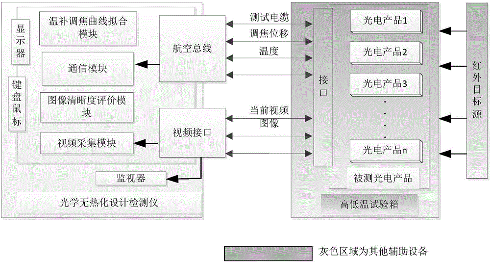
[0023] The purpose of the present invention is to provide an optical athermalization design detection system and detection method, which are used to detect and test the optimal focusing amount within the airborne ambient temperature range after the optical system is assembled into the optoelectronic product, through Temperature-compensated focusing test, using the image quality evaluation function to evaluate the image, find out the optimal focus curve under the airborne ambient temperature, and solidify the obtained temperature-compensated focusing curve inside the photoelectric product to realize the airborne ambient temperature. Athermalization design of the lower optical system.

[0024] like figure 1 As shown, the optical athermal design detection system...


PUM


Abstract

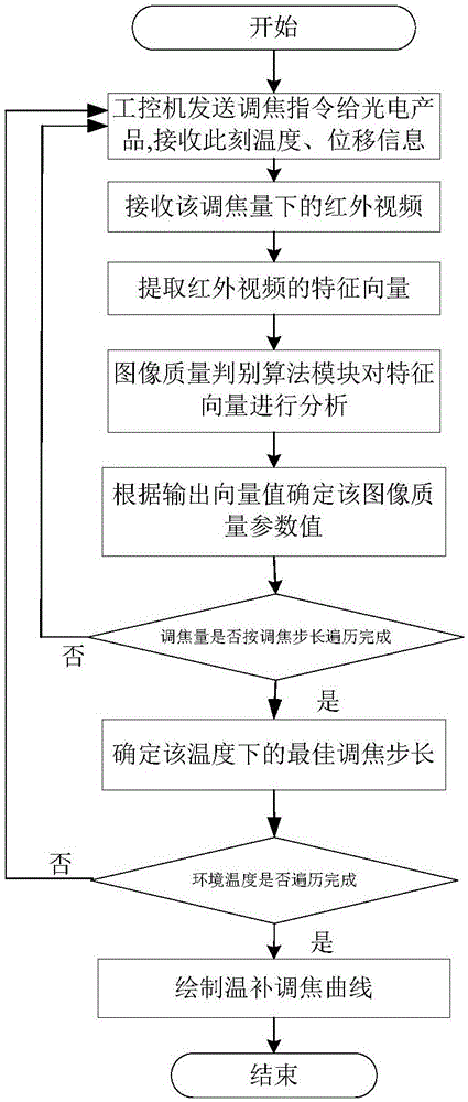
The invention provides an optical athermalization design detection system and detection method. The system comprises a communication module, a video acquisition module, an image definition evaluation module and a temperature compensation and focusing curve fitting module; the image definition evaluation module extracts the feature vectors of a video image in real time, analyzes the feature vectors according to an image quality discrimination algorithm, and obtains an optimal focusing quantity under a current temperature point when the image is has the highest definition through traversing a focusing range; and the temperature compensation and focusing curve fitting module fits an optimal focusing quantity curve in an entire airborne ambient temperature range according to optimal focusing quantities under different inputted temperature points. According to the optical athermalization design detection system and detection method of the invention, airborne ambient temperature is simulated, so that testing is performed; the optimal focusing quantity curve under different temperature is drawn, and is solidified into a photoelectric product, so that the athermalization design of an optical system can be realized. According to the detection system, image quality detection is objectively evaluated through adopting image definition, and a temperature compensation and focusing curve is automatically drawn, and therefore, labor and time can be saved. With the detection system and detection method adopted, multi-batch photoelectric products can be tested, so that repeatability is high.

Description

technical field [0001] The invention relates to the technical field of athermalization detection of an environmental optical system of an airborne photoelectric system, in particular to an athermalization design detection system and a detection method of an optical system. Background technique [0002] Usually, when designing an optical system, only the characteristics of optical materials under general conditions (normal temperature, normal pressure) are considered. However, for optical systems in an airborne environment, such as airborne photoelectric systems, the temperature, pressure, and solar radiation they bear are greatly different from those on the ground. Due to the influence of these factors, parameters such as the refractive index, thickness of the optical material, and the interval of the optical system will change, thereby causing changes in the imaging quality. [0003] The athermalization technology of the optical system is to use a certain temperature compe...

Claims


Application Information

Patent Timeline
Patent Type & Authority Applications(China)
IPC IPC(8): G01M11/00H04N5/232
CPCG01M11/00H04N23/67
Inventor 原玢张鹏冯长远翟方超耿国
Owner LUOYANG INST OF ELECTRO OPTICAL EQUIP OF AVIC
Learn More