
High-performance deep-stall wing structure and aircraft

A wing structure and deep stall technology, applied in the direction of wings, heat reduction structures, wing shapes, etc., can solve the problems of reduced lift and poor aerodynamic performance of aircraft, so as to improve the ability to resist flow separation, increase lift, The effect of improving aerodynamic performance

Active Publication Date: 2017-04-19
BEIHANG UNIV
View PDF7 Cites 9 Cited by
  • Summary
  • Abstract
  • Description
  • Claims
  • Application Information

AI Technical Summary

Problems solved by technology

[0004] However, in the prior art, although the uneven leading edge of the wing body eliminates the phenomenon of separation and stall of the wing body at a large angle of attack and improves the aerodynamic performance of the aircraft at a large angle of attack, this method will make the aircraft The maximum lift of the wing body and the lift force decrease at medium and small angles of attack, resulting in poor aerodynamic performance of the aircraft at medium and small angles of attack

Method used


Image

  • High-performance deep-stall wing structure and aircraft
  • High-performance deep-stall wing structure and aircraft
  • High-performance deep-stall wing structure and aircraft

Examples


Embodiment Construction

[0027] In order to make the purpose, technical solutions and advantages of the embodiments of the present invention clearer, the technical solutions in the embodiments of the present invention will be clearly and completely described below in conjunction with the drawings in the embodiments of the present invention. Obviously, the described embodiments It is a part of embodiments of the present invention, but not all embodiments. Based on the embodiments of the present invention, all other embodiments obtained by persons of ordinary skill in the art without making creative efforts belong to the protection scope of the present invention.

[0028] The terms "first", "second", "third", "fourth", etc. (if any) in the description and claims of the present invention and the above drawings are used to distinguish similar objects, and not necessarily Used to describe a specific sequence or sequence. It is to be understood that the data so used are interchangeable under appropriate ci...


PUM


Abstract

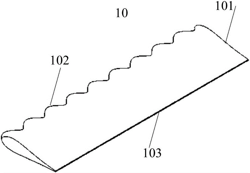
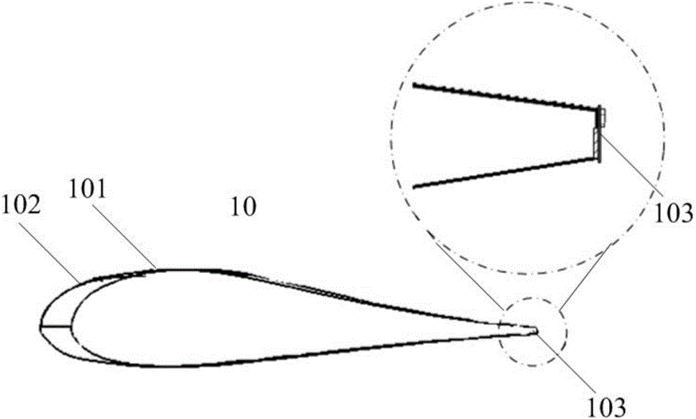
The invention provides a high-performance deep-stall wing structure and an aircraft, and belongs to the technical field of aeronautical facilities. The high-performance deep-stall wing structure comprises a wing body and a plasma exciter, the plasma exciter is attached to the back edge of the wing body, and the shape of the wing body is a preset waveform. By means of the high-performance deep-stall wing structure and the aircraft, the aerodynamic performance of the aircraft in the full attack angle scope is improved.

Description

technical field [0001] The invention relates to the technical field of aviation equipment, in particular to a high-performance deep-stall wing structure and an aircraft. Background technique [0002] In the field of aviation, improving the aerodynamic performance of aircraft has always been the focus of attention. Among them, the separation and stall of the wing body at high angles of attack will affect the aerodynamic performance of the aircraft, thereby endangering the safety of passengers. [0003] In the prior art, in order to solve the problem of separation and stall of the wing body at a large angle of attack, a conceptual design scheme is to transform the smooth leading edge of the original wing body into a bumpy leading edge, so that when the airflow flows through the wing At the leading edge of the wing body, a vortex will be rolled up from the concave to the convex. The vortex is elongated by the airflow in the flow direction and extends downstream. At the same ti...

Claims


Application Information

Patent Timeline
IPC IPC(8): B64C3/14B64C3/36B64C23/00
CPCB64C3/14B64C3/36B64C23/005B64C2003/146
Inventor 王晋军张增冯立好潘翀高琪
Owner BEIHANG UNIV
Learn More