Connector

A technology of connectors and connecting terminals, which is applied in the direction of connections, parts of connecting devices, coupling devices, etc., to achieve the effect of suppressing the possibility

Active Publication Date: 2017-04-05
DENSO CORP
View PDF9 Cites 0 Cited by
  • Summary
  • Abstract
  • Description
  • Claims
  • Application Information

AI Technical Summary

Problems solved by technology

[0005] In the connector with the above structure, the signal terminal may be inserted into the guide hole of the lower connector in an inclined state.

Method used


Image

  • Connector
  • Connector
  • Connector

Examples


Embodiment Construction

[0038] [summary]

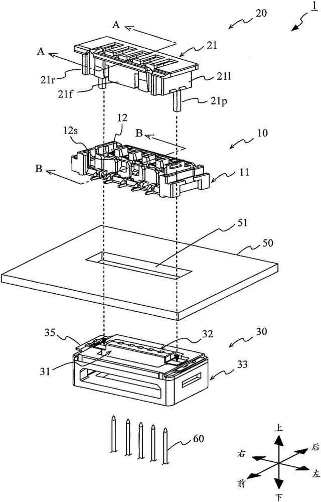
[0039] The connector of the present invention is a connector including an upper connector and a lower connector. This connector has two movable parts in the lower connector, and the two movable parts can obtain the following two states, that is, the first state in which the two movable parts are brought close to each other to form a guide hole for inserting an external signal terminal. ; and a second state in which the two movable parts are separated from each other from the external signal terminal. In this connector, a protrusion of a predetermined shape is provided at a position capable of contacting the two movable parts of the lower connector, and in the middle of the transition from the first state to the second state, the protrusion moves toward the two movable parts. The direction of separation from each other guides the two movable parts. Thereby, the two movable parts can be easily separated due to the synergistic effect of the guidance in the se...


PUM


Abstract

The invention relates to a connector. A housing of a lower connector has an opening on a side of an upper connector, and houses two movable parts movably from a first state of, by having upper portions thereof engaged with the opening, being in proximity to each other to form a guide hole, and a second state of, by releasing the engagement, being distanced from an external signal terminal. At positions contactable with the two movable parts, the housing has a protrusion whose tip gradually tapers toward the two movable parts in directions in which the two movable parts face each other. The protrusion guides the two movable parts in mutually separating directions, when the engagement between the opening of the housing and the upper portions of the two movable parts is released associated with depression of the upper connector, and the tip enters the gap through which the two movable parts face each other.

Description

technical field [0001] The present invention relates to a connector including an upper connector and a lower connector arranged above and below a substrate, and connecting an external signal terminal inserted from the lower connector side to the substrate via connection terminals of the upper connector. Background technique [0002] For example, Patent Document 1 (Japanese Unexamined Patent Application Publication No. 2014-154452) discloses a connector including a lower connector arranged on the lower surface of a substrate, and a connector arranged on the upper surface of the substrate and connected from The upper connector that connects the external signal terminals inserted in the lower connector side to the board. In this conventional connector, the lower connector includes two movable parts, and guide holes for guiding signal terminals inserted from the outside toward connection terminals of the upper connector are formed by bringing the two movable parts toward each ot...

Claims


Application Information

Patent Timeline
Patent Type & Authority Applications(China)
IPC IPC(8): H01R13/46H01R13/629
CPCH01R13/46H01R13/629H01R12/716H01R13/193H01R12/707H01R12/82H01R13/50H01R13/518
Inventor 尾崎仁
Owner DENSO CORP
Why Eureka
Try Eureka