Method for measuring both reflectivity of high-reflection optical element and transmittance of high-transmission optical element based on cavity ring-down technology

A ring-down technology for optical components and optical cavities, which is applied in the direction of transmittance measurement and scattering characteristic measurement, can solve the problems of measurement accuracy influence, complicated device, and inability to guarantee the position of the same component, and achieve the effect of reducing costs

Active Publication Date: 2017-04-05
UNIV OF ELECTRONICS SCI & TECH OF CHINA
View PDF12 Cites 13 Cited by
  • Summary
  • Abstract
  • Description
  • Claims
  • Application Information

AI Technical Summary

Problems solved by technology

Spectrophotometric technology can also be used to measure the reflectance of optical components, but the measurement accuracy is affected by the fluctuation of light source intensity, and the typical reflectance / transmittance measurement accuracy is ±0.1-0.3%
[0005] Using different devices to measure the single-point reflectance and transmittance of high-reflection / high-transmission optical components can neither ensure that the same component position is tested, nor that the optical components are in the same state, and the device is relatively complicated and cumbersome to operate
At present, there is no measurement method that can measure the reflectance and transmittance of high reflection / high transmission optical elements at the same time. The measurement device for reflectance / transmittance two-dimensional scanning imaging is very necessary

Method used


Image

  • Method for measuring both reflectivity of high-reflection optical element and transmittance of high-transmission optical element based on cavity ring-down technology
  • Method for measuring both reflectivity of high-reflection optical element and transmittance of high-transmission optical element based on cavity ring-down technology
  • Method for measuring both reflectivity of high-reflection optical element and transmittance of high-transmission optical element based on cavity ring-down technology

Examples


Embodiment Construction

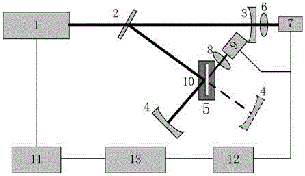
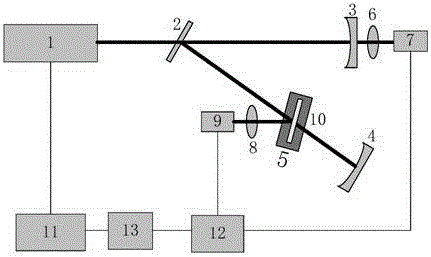
[0030] Combine below figure 1 and figure 2 The measurement system in which the initial optical cavity is a folded cavity describes a method for simultaneously measuring the reflectivity and transmittance of a high reflection / high transmission optical element based on the optical cavity ring-down technology of the present invention.

[0031]The light source 1 is a continuous semiconductor laser, and the function generator card 11 is used for square wave modulation output; according to the optical feedback optical cavity ring down technology, the laser is injected into a stable optical resonant cavity. A stable initial optical cavity is formed by a plane reflector 2 and two identical plano-concave reflectors 3 and 4 . The reflectivity of the mirrors forming the initial optical cavity is greater than 99%. The initial optical cavity is a stable optical resonant cavity with a cavity length L 0 satisfy 00 (A 01 , A 00 is a constant coefficient, t is time) to fit the ring-down ...


PUM

PropertyMeasurementUnit
reflectanceaaaaaaaaaa

Abstract

The invention relates to a method for measuring both the reflectivity of a high-reflection optical element and the transmittance of a high-transmission optical element based on cavity ring-down technology. The method comprises: through adoption of cavity ring-down technology, measuring a ring-down signal of an initial cavity and performing fitting to obtain a ring-down time of the initial cavity, adding a to-be-measured high-reflection / high-transmission optical element to form a stable measurement cavity, measuring a ring-down signal output from the to-be-measured optical element and a ring-down signal output from an output cavity mirror and performing fitting to obtain a ring-down time of the measured cavity, performing calculation to obtain the reflectivity of the high-reflection optical element or the transmittance of the high-transmission optical element; carrying out specific value calculation of the amplitude of a cavity ring-down signal output by the to-be-measured optical element and the amplitude of a cavity ring-down signal output by the output cavity mirror, and performing calibration to obtain the reflectivity of the high-reflection optical element or the transmittance of the high-transmission optical element. According to the method, the reflectivity of a high-reflection optical element and the transmittance of a high-transmission optical element can be measured, and high-resolution two-dimensional imaging of reflectivity and transmittance distribution is achieved.

Description

technical field [0001] The present invention relates to the technical field for measuring the reflectance / transmittance of high reflection optical elements or high transmission optical elements, in particular to a single point for simultaneously measuring high reflection optical elements or high transmission optical elements based on optical cavity ring down technology Method of reflectance / transmittance and its two-dimensional distribution of reflectance / transmittance. Background technique [0002] High reflection optical elements and high transmission optical elements are widely used in high power laser systems, gravitational wave detection, laser gyroscope and other technical fields. With the advancement of coating technology, the reflectance / transmittance of high reflection / high transmission optical components is getting higher and higher, and it is particularly important to accurately measure the reflectance / transmission of high reflection / high transmission optical comp...

Claims


Application Information

Patent Timeline
Patent Type & Authority Applications(China)
IPC IPC(8): G01N21/55G01N21/59
CPCG01N21/55G01N21/59
Inventor 李斌成崔浩王静
Owner UNIV OF ELECTRONICS SCI & TECH OF CHINA
Why Eureka
Try Eureka