
Compressor exhaust structure and compressor

A technology for compressor exhaust and exhaust passages, applied in the field of compressor accessories, can solve the problems of poor exhaust flow adjustment effect, affecting compressor energy efficiency, large noise and vibration, etc., to reduce gas flow rate, improve energy efficiency, improve effect of noise

Active Publication Date: 2018-11-23
GREE ELECTRIC APPLIANCES INC +1
View PDF5 Cites 0 Cited by
  • Summary
  • Abstract
  • Description
  • Claims
  • Application Information

AI Technical Summary

Problems solved by technology

[0003] 1. The noise and vibration generated by the collision between the valve plate 1' and the retaining plate 2' are relatively large;
[0004] 2. The exhaust flow adjustment effect of the exhaust hole 31' is poor. When the air flow velocity is high, it will generate a lot of noise, and when the air flow velocity is small, it will affect the energy efficiency of the compressor.

Method used


Image

  • Compressor exhaust structure and compressor
  • Compressor exhaust structure and compressor
  • Compressor exhaust structure and compressor

Examples


Embodiment Construction

[0030] The present invention is described below based on examples, but the present invention is not limited to these examples. In the following detailed description of the invention, some specific details are set forth in detail. The present invention can be fully understood by those skilled in the art without the description of these detailed parts. To avoid obscuring the essence of the present invention, well-known methods, procedures, procedures, and components have not been described in detail.

[0031] Additionally, those of ordinary skill in the art will appreciate that the drawings provided herein are for illustrative purposes and are not necessarily drawn to scale.

[0032] Unless the context clearly requires, throughout the specification and claims, "comprises", "comprises" and similar words should be interpreted in an inclusive sense rather than an exclusive or exhaustive meaning; that is, "including but not limited to" meaning.

[0033] In the description of the ...


PUM


Abstract

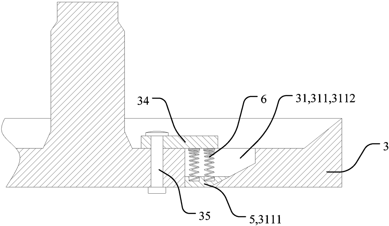
The invention discloses an exhaust structure of a compressor and the compressor. The exhaust structure of the compressor comprises a flange. An exhaust passageway is arranged on the flange. A valve block is arranged in the exhaust passageway and can at least move under the effect of the gas pressure in the exhaust passageway so that the opening degree of the exhaust passageway can be changed. According to the exhaust structure of the compressor, the valve block is arranged on the exhaust passageway and can move under the effect of the gas pressure in the exhaust passageway so that the opening degree of the exhaust passageway can be changed; when gas flow is large, the opening degree is increased, and therefore the flowing speed of gas can be decreased, and noise can be improved; and when the gas flow is small, the opening degree is decreased, and therefore the flowing speed of the gas is increased, and the energy efficiency of the compressor is improved.

Description

technical field [0001] The invention relates to the field of compressor accessories, in particular to a compressor exhaust structure and a compressor. Background technique [0002] Existing compressor exhaust structure such as figure 1 As shown in , the valve plate 1' and the baffle plate 2' are riveted together by the rivet 4', and fixed at the exhaust hole 31' of the flange 3'. When the compressor is running, the airflow impacts the valve plate 1' , so that the valve plate 1' opens the exhaust hole 31', the existing exhaust structure has the following problems: [0003] 1. The noise and vibration generated by the collision between the valve plate 1' and the retaining plate 2' are relatively large; [0004] 2. The exhaust flow adjustment effect of the exhaust hole 31' is poor. When the air flow velocity is high, it will generate a lot of noise, and when the air flow velocity is small, the energy efficiency of the compressor will be affected. Contents of the invention ...

Claims


Application Information

Patent Timeline
Patent Type & Authority Patents(China)
IPC IPC(8): F04B39/00F04B39/10
CPCF04B39/00F04B39/0027F04B39/10
Inventor 蒋姝婷范少稳
Owner GREE ELECTRIC APPLIANCES INC
Learn More