
Camera, manufacturing method thereof and terminal

A camera and terminal technology, applied in the optical field, can solve problems such as convex camera, large camera thickness, and poor thermal experience of end users, and achieve the effect of improving heat dissipation performance and reducing thickness

Inactive Publication Date: 2017-03-29
HUAWEI MACHINERY
View PDF6 Cites 4 Cited by
  • Summary
  • Abstract
  • Description
  • Claims
  • Application Information

AI Technical Summary

Problems solved by technology

The structural design of this camera makes the thickness of the camera very large, and assembling it into the terminal will inevitably affect the overall thickness of the terminal; if the overall size of the terminal is reduced, the camera will protrude, which will greatly affect the overall appearance of the terminal
[0003] Moreover, the heat consumption of the camera of the terminal with camera or camera function is generally large, the temperature of the position corresponding to the camera on the terminal shell will be high, and the thermal experience of the end user is very poor. In the existing technology, additional components are generally added to dissipate heat from the camera, while Additional components generally increase the thickness of the terminal

Method used


Image

  • Camera, manufacturing method thereof and terminal
  • Camera, manufacturing method thereof and terminal
  • Camera, manufacturing method thereof and terminal

Examples


Embodiment Construction

[0054] In order to make the purpose, technical solutions and advantages of the embodiments of the present invention clearer, the technical solutions in the embodiments of the present invention will be clearly and completely described below in conjunction with the drawings in the embodiments of the present invention. Obviously, the described embodiments It is a part of embodiments of the present invention, but not all embodiments. It should be noted that, based on the embodiments of the present invention, all other embodiments obtained by persons of ordinary skill in the art without creative work, as well as the embodiments of the present invention and the embodiments in the embodiments without conflict The mutual combinations of various modes all belong to the protection scope of the present invention.

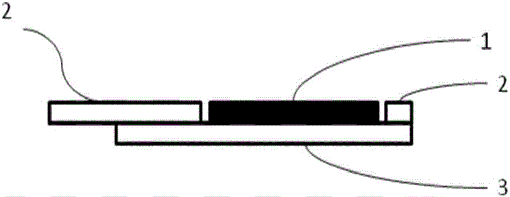
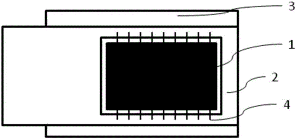
[0055] Figure 1a with Figure 1b A schematic structural diagram of a camera is provided for an embodiment of the present invention, Figure 1a is the side view of the camera...


PUM


Abstract

The present invention provides a camera. The camera comprises at least an image sensor, a flexible printed circuit board (FPC) and a substrate; the FPC is arranged on the substrate; a position on the FPC is hollowed out; the image sensor is fixed on a position on the substrate, wherein the position on the substrate is corresponding to the hollowed-out portion of the FPC; and the image sensor is connected with the FPC through a signal line. According to the camera provided by the technical schemes of the invention, the position on the FPC, which is corresponding to the image sensor, is hollowed out, and the FPC is mounted on the substrate, the image sensor is fixed at the position corresponding to the hollowed-out portion of the FPC, and therefore, the overall thickness of the camera can be reduced by the height of at least one FPC (120 microns).

Description

technical field [0001] The present invention relates to the field of optics, in particular to a camera, a manufacturing method thereof, and a terminal. Background technique [0002] "Thinness" is already one of the main fashion elements in the design of smart terminals, and end consumers are pursuing "thinness". Terminal manufacturers and suppliers are increasingly pursuing the manufacture and provision of thinner terminals. The thickness of the terminal generally depends on the maximum thickness of the component inside the terminal, and the terminal with camera or camera function generally depends on the thickness of the camera. Since the camera contains many components, generally, the module integrates a Voice Coil Motor (VCM for short, which includes auxiliary components such as coils and magnets), filters, image sensors, and printed circuit boards (Printed Circuit Boards). CircuitBoard (abbreviated as PCB), flexible printed circuit board (Flexible Printed Circuit Board,...

Claims


Application Information

Patent Timeline
Patent Type & Authority Applications(China)
IPC IPC(8): H04N5/225
CPCH04N23/54H04N23/57H04N23/00
Inventor 黄秋月康南波靳林芳
Owner HUAWEI MACHINERY
Learn More