A hydraulic support installation mechanism and its application

A technology of installation mechanism and hydraulic support, which is applied in mine roof support, mining equipment, earthwork drilling and mining, etc., can solve problems such as errors in the installation of hydraulic support, restrictions on the assembly process of hydraulic support, and high labor intensity of hydraulic support. The effect of economic benefits and market value, ingenious design and efficient installation

Active Publication Date: 2018-07-17
SHANDONG UNIV OF SCI & TECH
View PDF9 Cites 0 Cited by
  • Summary
  • Abstract
  • Description
  • Claims
  • Application Information

AI Technical Summary

Problems solved by technology

There are some disadvantages in this inventive device, its structure is too complicated, and the labor intensity of assembling the hydraulic support is relatively large
[0004] Chinese patent document CN201696064U discloses a hydraulic support assembly machine device, which includes a lifting and rotating mechanism, a rotating mechanism, a shunting mechanism, an undercarriage lifting mechanism, a lateral deflection adjustment mechanism, and a double-sided operating platform. The shortcomings of weak performance, the structure of the mechanism is small, so it is easy to make mistakes or even fail to meet the installation requirements for the installation of large hydraulic supports
[0005] All in all, although there are some hydraulic support assembly mechanisms, most of these mechanisms are manually installed, which is time-consuming and laborious.
By observing the on-site installation process of the hydraulic support, it is found that there are indeed some problems in the installation process, which seriously restrict the overall assembly process of the hydraulic support

Method used


Image

  • A hydraulic support installation mechanism and its application
  • A hydraulic support installation mechanism and its application
  • A hydraulic support installation mechanism and its application

Examples


Embodiment 1

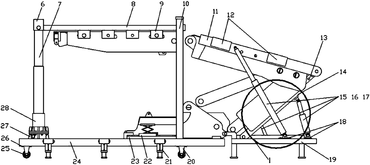
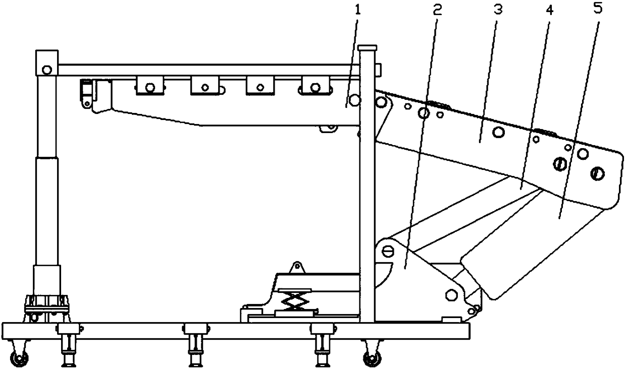
[0043] Such as Figure 1 to Figure 8 As shown, this embodiment provides a hydraulic support installation mechanism, including a top beam displacement mechanism and a cover beam assembly pushing mechanism, wherein:

[0044] The top beam displacement mechanism includes a scooter, a lifting device and a horizontal pushing device, the lifting device is arranged on the scooter, and the horizontal pushing device is arranged on the top of the lifting device;

[0045] The shielding beam assembly pushing mechanism includes base plate 19, load beam frame 11, the first pushing beam frame 13, the second pushing beam frame 14, the third pushing beam frame 68 and three telescopic support rods, the first pushing beam frame 13 One end is hinged with the load beam frame 11, the other end is connected with the second push beam frame 14, and the bottom ends of the second push beam frame 14 and the third push beam frame 68 are respectively hinged with the bottom plate 19; the load beam frame 11, ...

Embodiment 2

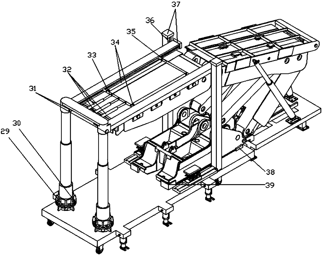
[0057] A hydraulic support installation mechanism, the structure is as described in Embodiment 1, the difference is that: the upper and lower sides of the car plate 24 are provided with lifting platform devices, and the lifting platform devices include slide rails 23, sliders 22, and a second horizontal push jack 45. Telescopic hinge 44 and support platform 46; one end of the slide rail 23 is connected with the bearing column 10 through the second pin 47, the slide block 22 is arranged on the slide rail 23, the top of the telescopic hinge 44 is connected with the bottom of the support platform 46, the bottom The end is connected with the slide block 22, and the horizontal second moving jack 45 is connected with the telescopic hinge 44. When the horizontal second moving jack 45 works, the telescopic hinge 44 is driven to extend or shrink in the vertical direction so as to drive the lifting of the supporting platform. The lifting table device provides some auxiliary functions for...

Embodiment 3

[0060] A hydraulic support installation mechanism, the structure is as described in Embodiment 2, the difference is that four positioning blocks are also arranged on the vehicle plate 24, and the four positioning blocks are symmetrically arranged on both sides of the lifting platform device and connected with the lifting platform The device is parallel, wherein two positioning blocks 38 are positioned at the right side of the lifting platform device, and two positioning blocks 39 are positioned at the left side of the lifting platform device (such as figure 2shown), the four positioning blocks can slide on the vehicle plate 24 (the vehicle plate is provided with corresponding grooves) to adjust the distance between the positioning blocks. Its advantages are that, firstly, the positioning block acts as a positioning guide for the base, so that after the base is moved in place, the mounting holes at the bottom ends of the front and rear connecting rods in the cover beam assembly...


PUM


Abstract

The invention relates to a hydraulic support installation mechanism and an application thereof. The hydraulic support installation mechanism comprises a top beam shifting mechanism and a shield beam assembly part pushing mechanism. The top beam shifting mechanism is used for supporting and moving a top beam, and the shield beam assembly part pushing mechanism is used for supporting and moving a shield beam, a front connecting rod and a rear connecting rod. The top beam shifting mechanism and the shield beam assembly part pushing mechanism are matched with each other to complete assembling of the top beam, a base, the shield beam, the front connecting rod and the rear connecting rod. The hydraulic support installation mechanism disclosed by the invention is ingenious in design and unique in structure, hydraulic supports can be integrally installed, and the installation requirements of most of the hydraulic supports can be met. The whole installation process is easy and convenient to operate, no manpower is required, installation efficiency is greatly improved, and meanwhile stability and safety of the whole installation process are high. The hydraulic support installation mechanism can be widely applied to installation of various models of hydraulic supports (namely at different heights) with the certain width range of the supports, wide generalization performance is achieved, and therefore the hydraulic supports can be installed safely and efficiently.

Description

technical field [0001] The invention relates to a hydraulic support installation mechanism and its application, and belongs to the technical field of hydraulic support fully mechanized mining equipment. Background technique [0002] The hydraulic support is one of the indispensable main equipments to realize the comprehensive mechanization and automation of coal mining. As the main equipment for supporting the surrounding rock in coal seam mining, the hydraulic support can prevent the roof from falling and maintain a safe working space by supporting the roof of the stope . In recent years, with the rapid development of high-efficiency fully mechanized mining technology in coal mining face and the increase of mining height of hydraulic support, the installation process of hydraulic support has become more and more complicated. Correspondingly, most of the existing devices for installing hydraulic support are large in size and complex in structure , The installation process t...

Claims


Application Information

Patent Timeline
Patent Type & Authority Patents(China)
IPC IPC(8): E21D23/16
CPCE21D23/16
Inventor 万丽荣孔帅孟昭胜岳宗兴杨扬李旭王刚杨延超张士奇王统诚
Owner SHANDONG UNIV OF SCI & TECH
Why Eureka
Try Eureka