
Controllable Counterweight System of Crawler Crane

A crawler crane, controllable technology, applied in the direction of cranes, ship accessories, passenger handling equipment, etc., can solve the main engine can not move, turn, transport, inconvenient disassembly and assembly, very high requirements for pulling plates, etc., to reduce material selection restrictions and cost, improve safety and reliability, and improve lifting efficiency

Active Publication Date: 2018-10-23
CHINA FIRST METALLURGICAL GROUP
View PDF10 Cites 0 Cited by
  • Summary
  • Abstract
  • Description
  • Claims
  • Application Information

AI Technical Summary

Problems solved by technology

[0002] At present, the 350-ton to 1000-ton crawler cranes on the market all use superlift counterweight mechanism to increase the rear moment. The rear host cannot move or rotate, and its performance is poor in terms of efficiency and reliability.
From the perspective of existing technology, for the design of medium and large tonnage, the structure, control and method of increasing the rear moment have become bottlenecks

Method used


Image

  • Controllable Counterweight System of Crawler Crane
  • Controllable Counterweight System of Crawler Crane
  • Controllable Counterweight System of Crawler Crane

Examples


Embodiment Construction

[0033] In order to make the object, technical solution and advantages of the present invention clearer, the present invention will be further described in detail below in conjunction with the accompanying drawings and embodiments. It should be understood that the specific embodiments described here are only used to explain the present invention, not to limit the present invention.

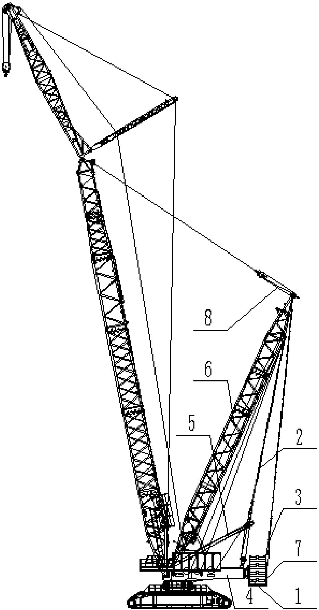
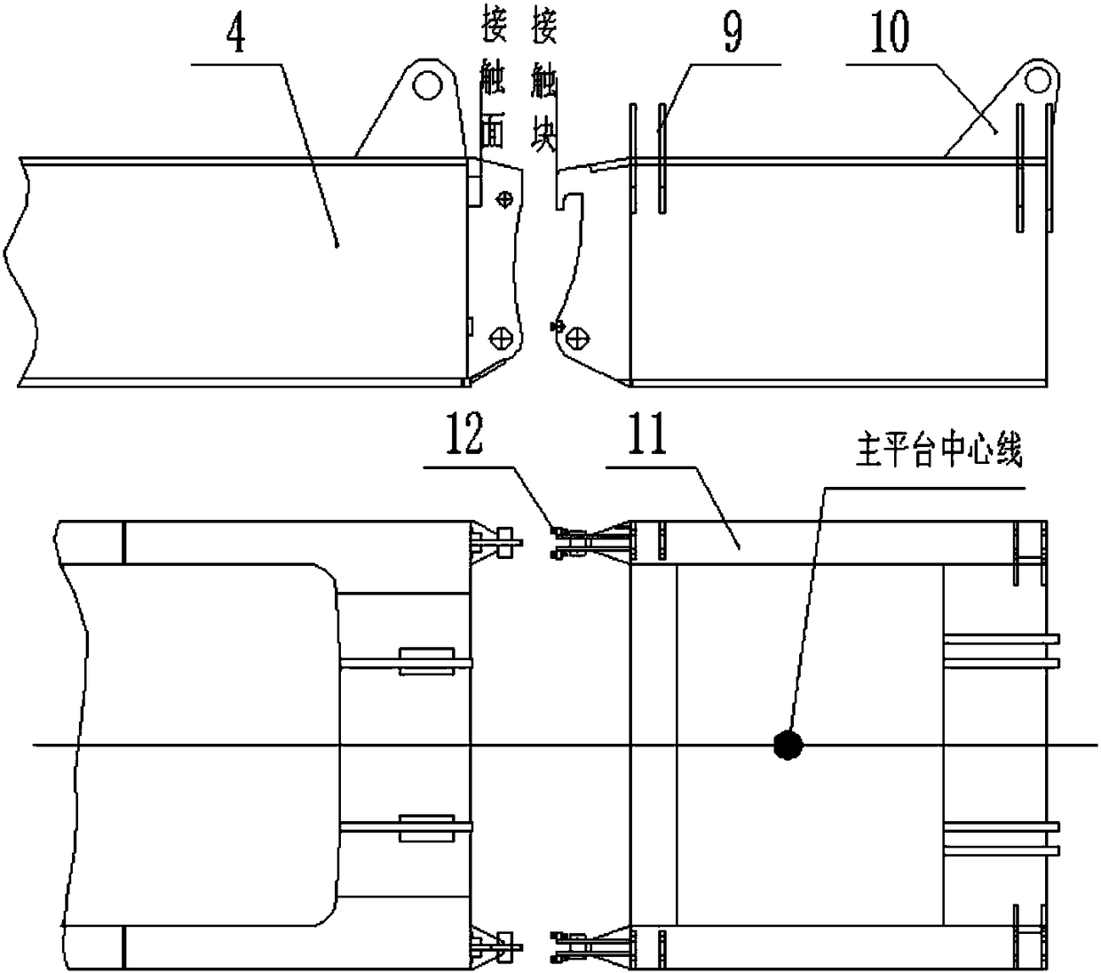
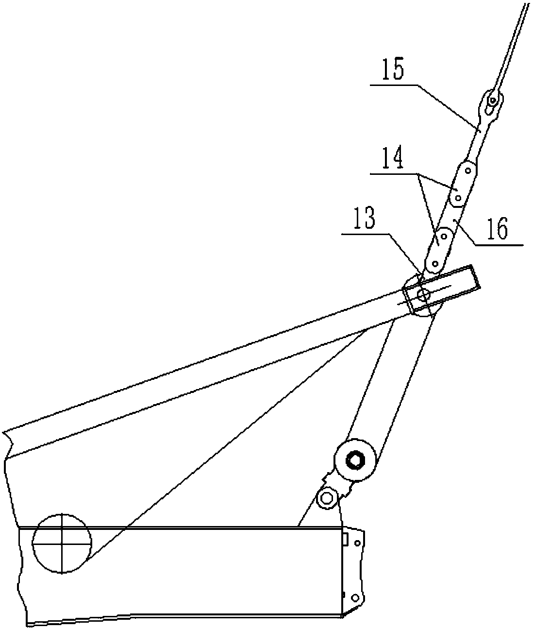
[0034] join Figure 1-Figure 7 , a controllable counterweight system for a crawler crane, including a main puller device 2, an auxiliary puller device 3, an extension bracket device 1, a controller, a tension sensor 16, and a pin sensor 18. The main pull plate device 2 includes a first transition pull plate 13, a second transition pull plate 14, and a main combined pull plate 15. The upper end of the second transition draw plate 14 of the lower end of the draw plate 15 is hinged, and the lower end of the second transition draw plate 14 is connected with the upper end of the first transition draw p...


PUM


Abstract

The invention discloses a controllable counterweight system of a crawler crane. The controllable counterweight system comprises main pulling plate devices, auxiliary pulling plate devices, an extending supporting frame device and a controller. A super-lift mast and a luffing device are hinged to the upper ends of the main pulling plate devices, and a small mast is hinged to the lower ends of the main pulling plate devices. A tension sensor is arranged on each main pulling plate device. Each auxiliary pulling plate device comprises an auxiliary combined pulling plate and a telescopic unit. The super-lift mast and the luffing device are hinged to the upper ends of the auxiliary combined pulling plates. The upper end of a telescopic piece of each telescopic unit is hinged to the lower end of the corresponding auxiliary combined pulling plate. The lower ends of the telescopic pieces of the telescopic units are connected with a supporting frame of the extending supporting frame device. A hinge pin sensor is arranged on each auxiliary pulling plate device. The extending supporting frame device comprises the supporting frame used for placing of a counterweight mechanism. The supporting frame is connected with a main platform of the crawler crane. Data are transmitted to the controller through the tension sensors and the hinge pin sensors. The extending and retracting of the telescopic pieces are controlled by the controller. According to the controllable counterweight system of the crawler crane, the safety and reliability of the crawler crane are improved.

Description

technical field [0001] The invention belongs to the technical field of crawler cranes, and in particular relates to a controllable counterweight system of crawler cranes. Background technique [0002] At present, the 350-ton to 1000-ton crawler cranes on the market all use superlift counterweight mechanism to increase the rear moment. The rear host cannot move or rotate, and has poor performance in terms of efficiency and reliability. From the prior art, for the design of medium and large tonnage, the structure, control and method of increasing the rear moment have become bottlenecks. Contents of the invention [0003] The purpose of the present invention is to provide a controllable counterweight system for crawler cranes. This mechanism can replace the traditional super-lifting counterweight mechanism, solve the difficult problem of difficult material selection and high price for pull plates in the market, and is beneficial to improve the hoisting of crawler cranes. , ...

Claims


Application Information

Patent Timeline
Patent Type & Authority Patents(China)
IPC IPC(8): B66C23/76B66C23/60
CPCB66C23/60B66C23/76B66C2700/0392
Inventor 李前国罗琰峰田静沈健胡传福
Owner CHINA FIRST METALLURGICAL GROUP
Learn More