Rapid electronic equipment packing device

An electronic device and fast technology, applied in packaging, transportation packaging, transportation and packaging, etc., can solve the problems of unusable, low production efficiency, easy to be polluted, etc., to improve efficiency, increase vacuum rate, and prevent air residue Effect

Inactive Publication Date: 2017-03-29
芜湖光荣网络科技有限公司
View PDF7 Cites 0 Cited by
  • Summary
  • Abstract
  • Description
  • Claims
  • Application Information

AI Technical Summary

Problems solved by technology

However, traditional manual packaging is generally used, and the production efficiency is very low. At the same time, few companies use vacuum packaging, so that there is a lot of air in the packaging film inside some electronic equipment, so it is easy for some electronic equipment that is easy to oxidize. polluted, even unusable

Method used


Image

  • Rapid electronic equipment packing device
  • Rapid electronic equipment packing device
  • Rapid electronic equipment packing device

Examples


Embodiment Construction

[0019] The following will clearly and completely describe the technical solutions in the embodiments of the present invention with reference to the accompanying drawings in the embodiments of the present invention. Obviously, the described embodiments are only some, not all, embodiments of the present invention.

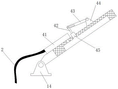
[0020] refer to Figure 1-4 , a rapid packaging device for electronic equipment, comprising a workbench 8, a guide groove is provided above the workbench 8, a conveyor belt 7 is installed in the guide groove, and evenly arranged trays 6 are arranged above the conveyor belt 7, and a tray 6 is arranged above the tray 6 Storage tank, the bottom of the storage tank is provided with a lower heating strip 5, the top of the workbench 8 is located on one side of the guide groove, and two first hinge seats 14 arranged in parallel are installed, and a cover is hinged between the first hinge seats 14 One end of the plate 4, the cover plate 4 is provided with a groove near the s...


PUM


Abstract

The invention discloses a rapid electronic equipment packing device which comprises a worktable. A guide groove is formed in the upper portion of the worktable and internally provided with a conveyer belt. Trays are uniformly arranged on the conveyer belt. A storage groove is formed in the upper portion of each tray. A lower heating strip is arranged at the bottom of each storage groove. Two parallel first hinge bases are mounted at the positions, located on one side of the guiding groove, of the upper portion of the worktable. One end of a cover plate is hinged between the first hinge bases. A groove is formed in the side edge, close to the worktable, of the cover plate. A vacuum hole is formed in the bottom of the groove. A mounting hole is formed in the side, away from the first hinge bases, of the vacuum hole and located at the bottom of the groove. A buffer tank is mounted at the end, away from the worktable, of the vacuum hole. An inner cavity of the buffer tank communicates with the vacuum hole. A vacuum pipe is mounted on the buffer tank and communicates with the inner cavity of the buffer tank. By adoption of the rapid electronic equipment packing device, manual placement of an electronic equipment sample can be omitted, assembly line operation is achieved, and the packing efficiency is improved.

Description

technical field [0001] The invention relates to the technical field of electronic equipment, in particular to a fast packaging device for electronic equipment. Background technique [0002] Electronic devices are widely used in our daily life and work, bringing convenience to people's lives. [0003] The packaging of electronic equipment is generally wrapped inside the packaging film, and then placed in a carton or plastic box for final packaging. However, traditional manual packaging is generally used, and the production efficiency is very low. At the same time, few companies use vacuum packaging, so that there is a lot of air in the packaging film inside some electronic equipment, so it is easy for some electronic equipment that is easy to oxidize. Polluted, even unusable. Contents of the invention [0004] The purpose of the present invention is to solve the shortcomings in the prior art, and propose a quick packaging device for electronic equipment. [0005] In orde...

Claims


Application Information

Patent Timeline
Patent Type & Authority Applications(China)
IPC IPC(8): B65B31/06B65B51/10
CPCB65B31/06B65B51/10
Inventor 武纪东张玉
Owner 芜湖光荣网络科技有限公司
Why Eureka
Try Eureka