A transformer magnetic balance method and device for a multi-state switch circuit

A multi-state switch and transformer technology, applied in the direction of output power conversion devices, electrical components, etc., can solve problems such as bombing, low-frequency voltage difference, and inductance deviation

Active Publication Date: 2018-10-09
VERTIV CORP
View PDF6 Cites 0 Cited by
  • Summary
  • Abstract
  • Description
  • Claims
  • Application Information

AI Technical Summary

Problems solved by technology

Although the magnetic coupling characteristics of the transformer itself in the multi-state switch structure can realize the current sharing control of the common-mode current, due to the discreteness of the system device parameters, the deviation of the inductance, the voltage change, the driving delay, and the dead time, etc., Will create a low frequency voltage drop across the transformer in a multi-state switching configuration
When the product of amplitude and seconds generated by the pressure difference exceeds the allowable value of the magnetic core, it will cause the transformer to saturate, resulting in that the maximum magnetic induction intensity B value of the actual transformer is much higher than the theoretically calculated magnetic induction intensity B value. In severe cases, it will cause Fryer problem

Method used


Image

  • A transformer magnetic balance method and device for a multi-state switch circuit
  • A transformer magnetic balance method and device for a multi-state switch circuit
  • A transformer magnetic balance method and device for a multi-state switch circuit

Examples


Embodiment Construction

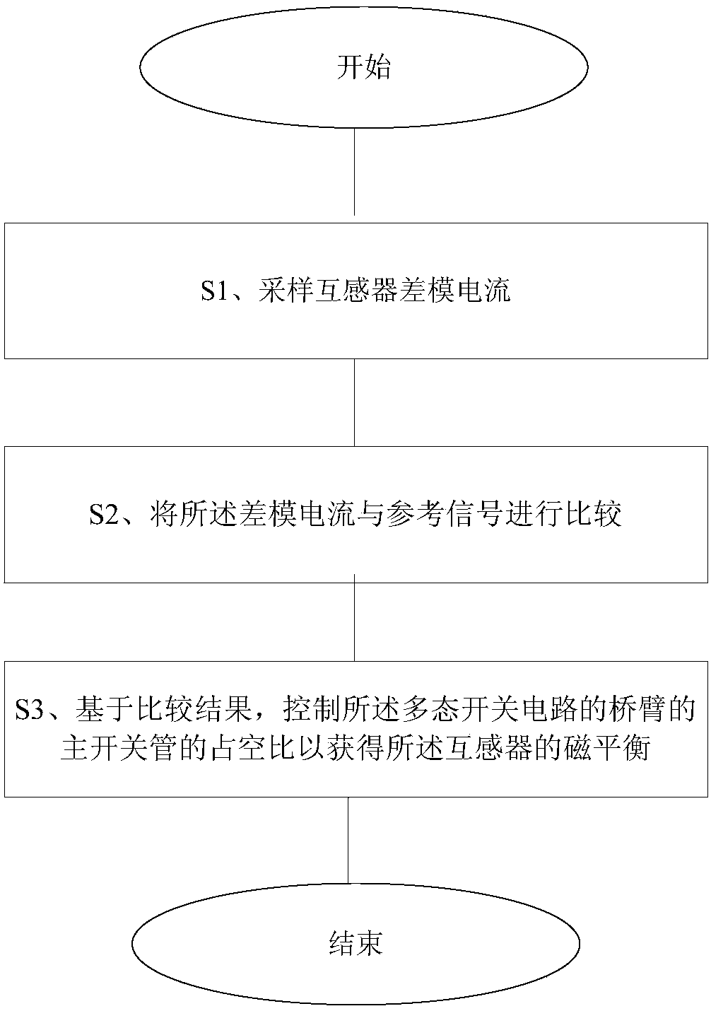
[0062] Such as figure 1As shown, a transformer magnetic balance method for a multi-state switch circuit of the present invention. In step S1, the differential mode current of the transformer is sampled by the sampling module. In the present invention, various methods can be used to sample the differential mode current of the transformer. In an embodiment of the present invention, the total current of multiple bridge arms of the multi-state switch circuit may be sampled first. Then sample the bridge arm current on any bridge arm. Next, the total current may be divided by the number of bridge arms of the plurality of bridge arms to obtain an average current of the bridge arms. Finally, the bridge arm average current is subtracted from the bridge arm current to obtain the differential mode current. In another embodiment of the present invention, the current of the first bridge arm of the first bridge arm of the multi-state switch circuit may be sampled first. Then sampling t...


PUM


Abstract

The invention relates to a transformer magnetic balance method for a multi-state switch circuit, comprising: S1, sampling the differential mode current of the transformer; S2, comparing the differential mode current with a reference signal; S3, controlling the The duty cycle of the main switch tube of the bridge arm of the multi-state switch circuit is used to obtain the magnetic balance of the transformer. Implement the transformer magnetic balance method and device of the multi-state switch circuit of the present invention, by sampling the differential mode current of the transformer, control the duty cycle of the main switch tube of the bridge arm of the multi-state switch circuit, and then obtain the mutual inductance The magnetic balance of the device.

Description

technical field [0001] The invention relates to a multi-state switch circuit, more specifically, to a method and device for magnetic balance of a transformer of a multi-state switch circuit. Background technique [0002] The multi-state switch structure usually includes a transformer and a set of bridge arms composed of diodes and switch tubes. Although the magnetic coupling characteristics of the transformer itself in the multi-state switch structure can realize the current sharing control of the common mode current, due to the discreteness of the system device parameters, inductance deviation, voltage change, drive delay, dead time and other reasons, A low-frequency voltage drop will develop across the transformers in the multi-state switching configuration. When the product of amplitude and seconds generated by the pressure difference exceeds the allowable value of the magnetic core, it will cause the transformer to saturate, resulting in that the maximum magnetic induct...

Claims


Application Information

Patent Timeline
Patent Type & Authority Patents(China)
IPC IPC(8): H02M1/40
Inventor 毛云鹤
Owner VERTIV CORP
Why Eureka
Try Eureka