
Driving method for touch control display panel, touch control display panel and touch control display device

A technology of a touch display panel and a driving method, which is applied to the driving of the touch display panel, the touch display panel and the touch display device field, can solve the problem of the low point reporting rate of the touch display panel and the long time required for the touch scan. And other issues

Active Publication Date: 2017-03-22
XIAMEN TIANMA MICRO ELECTRONICS +1
View PDF9 Cites 7 Cited by
  • Summary
  • Abstract
  • Description
  • Claims
  • Application Information

AI Technical Summary

Problems solved by technology

In the existing touch display panel, when a touch operation occurs on the touch display panel, the driver chip usually needs to output touch scanning signals to each touch electrode one by one to detect the position of the touch electrode where the touch operation occurs, resulting in In addition to the long time required for touch scanning, the reporting rate of the touch display panel is low

Method used


Image

  • Driving method for touch control display panel, touch control display panel and touch control display device
  • Driving method for touch control display panel, touch control display panel and touch control display device
  • Driving method for touch control display panel, touch control display panel and touch control display device

Examples


Embodiment Construction

[0016] The principles and features of the present application will be further described in detail below with reference to the accompanying drawings and embodiments. It should be understood that the specific embodiments described herein are only used to explain the related invention, but not to limit the invention. In addition, it should be noted that, for the convenience of description, only the parts related to the invention are shown in the drawings.

[0017] It should be noted that the embodiments in the present application and the features of the embodiments may be combined with each other in the case of no conflict. The present application will be described in detail below with reference to the accompanying drawings and in conjunction with the embodiments.

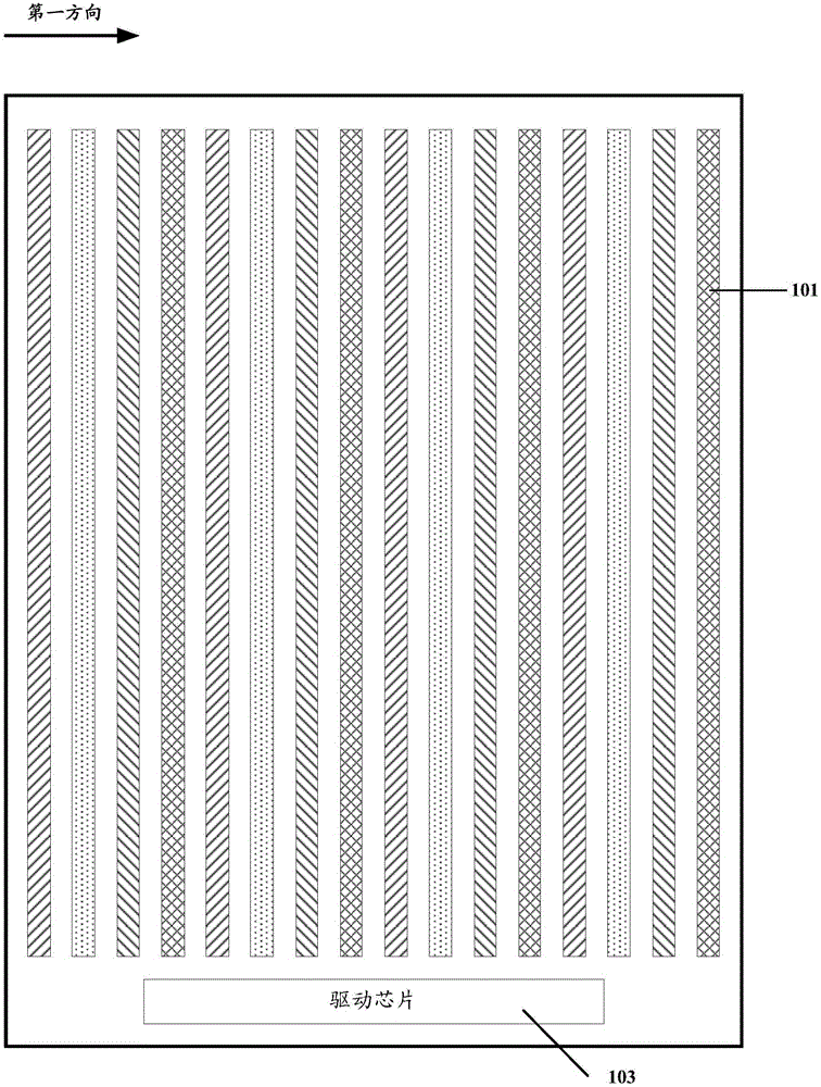
[0018] The present application adopts an improved driving method of a touch display panel, which shortens the scanning time of the touch electrodes. like Figure 1A As shown, it shows a flowchart 1000 of an embodime...


PUM


Abstract

The invention discloses a driving method for a touch control display panel, the touch control display panel and a touch control display device. The touch control display panel comprises a No.1 touch control electrode to a No.N touch control electrode, a driving chip which are sequentially arranged in the first direction. The driving method comprises that the driving chip divides the No.1 touch control electrode to the No.N touch control electrode into a No.1 first touch control electrode group to a No.m1 first touch control electrode group to carry out first time touch control scanning, all the touch control electrodes in each first touch control electrode group receive a touch control scanning signal of the driving chip at the same time, the driving chip divides the No.1 touch control electrode to the No.N touch control electrode into a No.1 second touch control electrode group to a No.m2 second touch control electrode group to carry out second time touch control scanning, all the touch control electrodes in each second touch control electrode group receive the touch control scanning signal of the driving chip at the same time, a No.j second touch control electrode group and a No.i first touch control electrode group at least include one same touch control electrode, and m1+m2<N. By employing the above driving method, the scanning time of the touch control electrodes can be reduced, and the contact reporting rate of the touch control display panel can be increased.

Description

technical field [0001] The present application relates to the field of display technology, and in particular, to a driving method of a touch display panel, as well as a touch display panel and a touch display device. Background technique [0002] With the rapid development of display technology, touch display technology has gradually spread throughout people's lives. The touch display panel allows the user to input user instructions directly by hand or with the help of external objects, and then select the displayed content. When a user touches the touch display panel with a hand or a foreign object, the touch display panel can detect the touch point, and drive the touch display device according to the input instruction to realize a specific display. [0003] The existing touch display panel can be provided with a plurality of strip-shaped touch electrodes, and each touch electrode can be electrically connected to the driving chip through the electrode leads, and the drivin...

Claims


Application Information

Patent Timeline
IPC IPC(8): G06F3/041
CPCG06F3/0416
Inventor 郑志伟杨康鹏许育民曹兆铿
Owner XIAMEN TIANMA MICRO ELECTRONICS
Learn More