Through shaft type tension sensor

A technology of tension sensor and shaft threading, applied in tension measurement, instrument, measurement force, etc., can solve the problems of poor accuracy, high maintenance cost, short long-term service life, etc., and achieve long service life, high precision and good stability. Effect

Inactive Publication Date: 2017-03-22
安徽中航电子科技发展有限公司
View PDF8 Cites 6 Cited by
  • Summary
  • Abstract
  • Description
  • Claims
  • Application Information

AI Technical Summary

Problems solved by technology

The disadvantages of this sensor are: poor accuracy, poor stability, short long-term service life, and high maintenance costs

Method used


Image

  • Through shaft type tension sensor
  • Through shaft type tension sensor
  • Through shaft type tension sensor

Examples


no. 1 example

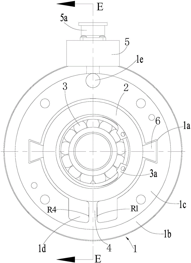
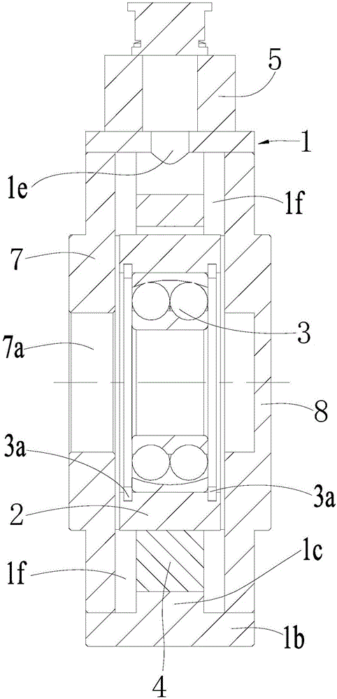
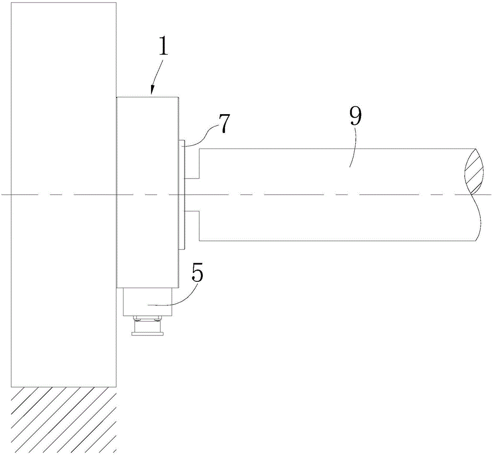
[0048] see figure 1 — Figure 4 , The sensor includes a shell 1, a circular bearing frame 2, a self-aligning bearing 3, a strain beam 4, a control circuit, an output interface 5, an inner plate 7, and an outer plate 8.

[0049] The housing 1 is formed by connecting a circular inner ring 1c and an outer ring 1b coaxially. The axial thickness of the inner ring 1c is smaller than the axial thickness of the outer ring 1b, and the inner ring 1c is located in the axial middle area of ​​the outer ring 1b. Two recesses 1f are formed on both sides in the axial direction between the inner ring 1c and the outer ring 1b, and the two recesses 1f are the inside of the housing 1 .

[0050] The bearing frame 2 is coaxially located in the inner ring 1c with a gap between them, the gap is 3-5 mm, and the axial thickness of the bearing frame 2 is between the axial thickness of the inner ring 1c and the axial thickness of the outer ring 1b. Between the thickness, the self-aligning bearing 3 is ...

no. 2 example

[0065] see Figure 5 , compared with the first embodiment, the second embodiment only has a different cross-sectional shape of the protrusion 6 along the radial direction of the bearing frame 2 .

[0066] For the cross-sectional shape of the projection 6 along the radial direction of the bearing frame 2 is a large semicircle, the cylindrical surface of the large semicircle is in an overhanging state, and the radial extension length of the large semicircle is equal to the radial extension length of the strain beam 4 The ratio is (0.5-0.7):1, and the ratio of the width of the large semicircle to the width of the strain beam 4 is (3.1-3.3):1.

no. 3 example

[0068] see Figure 6 , compared with the first embodiment, only the cross-sectional shape of the protrusion 6 along the radial direction of the bearing frame 2 is different in the third embodiment.

[0069] For the cross-sectional shape of the projection 6 along the radial direction of the bearing frame 2 is a half-waist circle, the cylindrical surface of the half-waist circle is in an overhanging state, and the radial extension length of the half-waist circle is the same as that of the strain beam 4 The ratio of the radial extension length of the beam is (0.8-1):1, and the ratio of the width of the half girdle to the width of the strain beam 4 is (3.1-3.3):1.


PUM


Abstract

The invention provides a through shaft type tension sensor. The through shaft type tension sensor is characterized in that a bearing bracket is arranged in a shell; self-aligning bearings are arranged in the bearing bracket; two lugs are arranged outside the bearing bracket; the section shapes of the lugs are any one of isosceles trapezoid, large semicircle, half waist circle and half oval; two matched clamp slots and a strain beam connected with the bearing bracket and the shell are formed in the shell; resistance strain gauges R1-R4 are arranged on the strain beam; the section shape of the strain beam is rectangular; an output interface is arranged outside the shell and is communicated with the interior of the shell; a control circuit comprises the resistance strain gauges R1-R4, a zero temperature compensation resistor Rt, a zero output compensation resistor Rz, an input consistency compensation resistor Ri, two parallel sensitivity output compensation resistors RL and two parallel sensitivity temperature compensation resistors Rb; a power line and an output signal line of the control circuit are laid in the shell and are connected with the output interface; inner and outer side plates are arranged at the two axial sides of the shell. The sensor has high precision, good stability and long service life.

Description

technical field [0001] The invention relates to a shaft-through tension sensor. Background technique [0002] At present, the working principle of the existing differential transformer tension sensor is: insert the iron core into the coil, apply downward pressure to the sensor through the guide roller and the bearing seat, so that the iron core generates displacement in the coil, Output a voltage signal. The disadvantages of this sensor are: poor precision, poor stability, short long-term service life, and high maintenance costs. Contents of the invention [0003] The technical problem to be solved by the present invention is to provide a shaft-through tension sensor, which has the advantages of high precision, good stability and long service life. [0004] In order to solve the above technical problems, the present invention provides a shaft-through tension sensor, which includes a housing, a bearing frame, a self-aligning bearing, a strain beam, a control circuit, an o...

Claims


Application Information

Patent Timeline
Patent Type & Authority Applications(China)
IPC IPC(8): G01L5/10G01L1/22
CPCG01L1/22G01L5/101
Inventor 崔普江
Owner 安徽中航电子科技发展有限公司
Why Eureka
Try Eureka