
Drawer type suction port of integrated stove

A suction port and drawer-type technology, which is applied in the field of integrated stoves, can solve the problems that the top suction plate occupies a certain space, the air port is small, and the effect of blowing or smoking is poor.

Active Publication Date: 2018-07-20
林志斌
View PDF1 Cites 0 Cited by
  • Summary
  • Abstract
  • Description
  • Claims
  • Application Information

AI Technical Summary

Problems solved by technology

For range hoods with integrated stoves, a side suction plate is usually arranged on the stove top, and there are side suction holes on the side suction plate, and a top suction plate is formed on the side suction plate, and the top suction plate The top suction hole is made, and the oil fume is sucked through the side suction hole and the top suction hole. The disadvantages of this structure are: first, the top suction plate needs to be made to protrude so that the top suction hole can be sucked up. and the protruding top air suction board takes up a certain space; second, when people are frying and so on, when the oil fume is large, some of the oil fume will float in the direction of the person standing, and away from the negative side of the side suction air hole. The nip area is not sucked by the side suction port, the fume extraction effect is poor, which affects the sanitation of the kitchen, and the fumes floating out are easy to choke people
Therefore, the applicant has applied for a Chinese invention patent 201410744153.7, the patent name is "Blowing and Suction Double Rotating Rods Stepless Positioning Integrated Stove", which is provided with two rotating rods on the top of the side suction plate, and the through hole at one end of the rotating rod Connect the air curtain machine or wind wheel, the two rotating rods can be one for blowing, one for oil suction, or both for blowing, or both for oil suction, and according to the needs of cooking, rotate and adjust the rotating rod at will, However, the volume of the rotary rod of this structure is small, and the tuyere is also small, so the effect of blowing or smoking is poor

Method used


Image

  • Drawer type suction port of integrated stove
  • Drawer type suction port of integrated stove
  • Drawer type suction port of integrated stove

Examples


Embodiment Construction

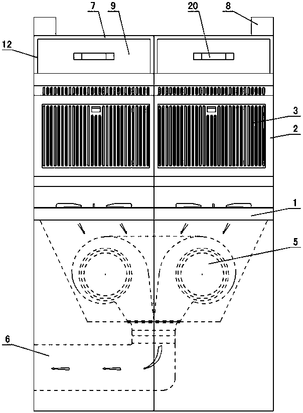
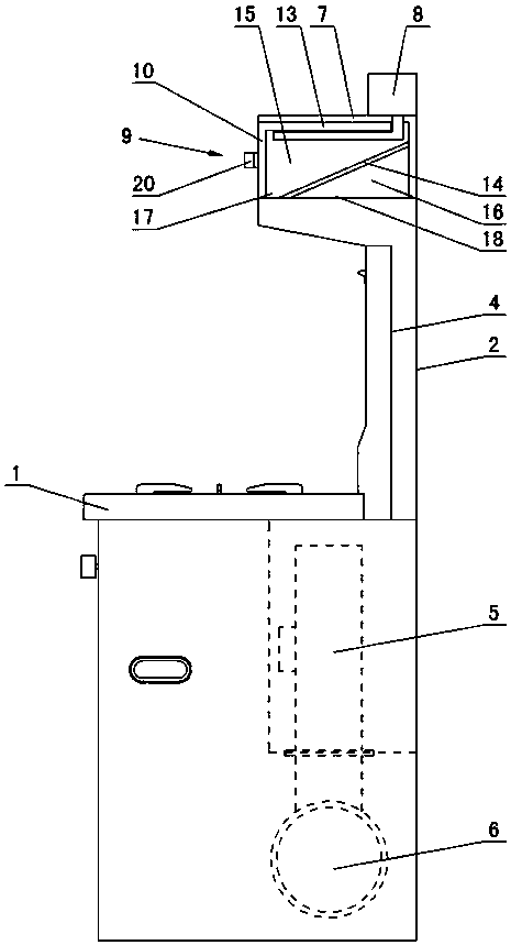
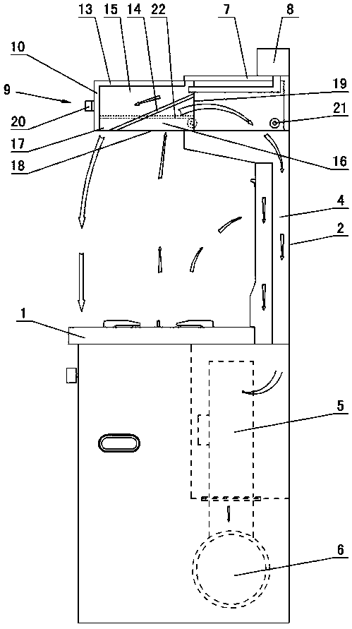
[0010] The invention relates to a drawer-type air suction port of an integrated stove, such as figure 1 — image 3 As shown, it includes a stove 1, a side suction plate 2 is arranged on the stove, a side suction hole 3 is formed on the wall of the side suction plate, an air suction channel 4 is opened in the side suction plate, a wind wheel 5 is arranged in the stove, The wind wheel is connected to the air outlet 6, and it is characterized in that: a top box 7 is arranged on the top of the side suction plate 2, an air curtain machine 8 is arranged on the top box, openings are formed on the front side and the lower side of the top box, and the top box Draw box 9 is set in the middle, and draw box is shaped on front baffle plate 10, both sides baffle plate 12 and upper baffle plate 13, and front baffle plate cooperates with the opening of top box front side, and inclined guide plate 14 is set in draw box, and inclined guide plate The inner cavity of the draw box 9 is divided in...


PUM


Abstract

A drawer type exhaust inlet of an integrated stove comprises a stove platform. A side suction plate is arranged on the stove platform, side suction holes are formed in the wall of the side suction plate, a suction channel is formed in the side suction plate, and an air wheel is arranged in the stove platform and connected with an air outlet. The drawer type exhaust inlet of the integrated stove is characterized in that a top box is arranged on the top of the side suction plate, an air curtain machine is arranged on the top box, openings are formed in the front side and the lower side of the top box, a pull box is arranged in the top box, a front baffle, two side baffles and an upper baffle are arranged on the pull box, the front baffle is matched with the opening in the front side of the top box, an oblique guide plate is arranged in the pull box, an inner cavity of the pull box is divided into an upper air curtain cavity and a lower suction cavity by the oblique guide plate, the upper air curtain cavity communicates with the air curtain machine, an air opening is formed in the lower side of the pull box and is divided into a blowing opening and a suction opening by the oblique guide plate, a ventilation opening is formed in the rear side of the pull box, the blowing opening communicates with the upper air curtain, the suction opening communicates with the lower suction cavity, and the lower suction cavity communicates with the suction channel through the ventilation opening.

Description

technical field [0001] The invention relates to an integrated cooker, in particular to a drawer-type air suction port of the integrated cooker. Background technique [0002] The integrated stove is a kitchen appliance that integrates multiple functions such as a range hood, a gas stove, and a storage cabinet. It has the advantages of space saving, convenient use, energy saving, low consumption, and environmental protection. It is widely used in current home kitchens. For range hoods with integrated stoves, a side suction plate is usually arranged on the stove top, and there are side suction holes on the side suction plate, and a top suction plate is formed on the side suction plate, and the top suction plate The top suction hole is made, and the oil fume is sucked through the side suction hole and the top suction hole. The disadvantages of this structure are: first, the top suction plate needs to be made to protrude so that the top suction hole can be sucked up. and the pro...

Claims


Application Information

Patent Timeline
Patent Type & Authority Patents(China)
IPC IPC(8): F24C15/20
CPCF24C15/2042
Inventor 林志斌
Owner 林志斌
Learn More