Structure of end part of weather strip and the forming method thereof

A technology of end structure and sealing strip, which is applied in the direction of sealing device, engine sealing, wing fan operating mechanism, etc., can solve the problem of sealing strip not being installed in a stable state, and achieve the effect of strong fitting force

Active Publication Date: 2017-03-22
NISHIKAWA RUBBER
View PDF8 Cites 2 Cited by
  • Summary
  • Abstract
  • Description
  • Claims
  • Application Information

AI Technical Summary

Problems solved by technology

[0007] In addition, there is known a structure in which a notch is deliberately provided on the bent portion of the flange 101 to provide a weather strip with a sensor ( FIG. 11 of Patent Document 1), but there is a problem that the notch of the flange 101 is not sealed. strip cannot be installed in a stable state
[0008] In addition, there is known a structure in which a bracket is used to connect the upper flange and the lower flange at the part of the flange 101 that is interrupted in the middle (Patent Document 2 Figure 8 ), but since the bracket and the weather strip are different components, it is not a structure to extend the weather strip with the sensor

Method used


Image

  • Structure of end part of weather strip and the forming method thereof
  • Structure of end part of weather strip and the forming method thereof
  • Structure of end part of weather strip and the forming method thereof

Examples


Embodiment Construction

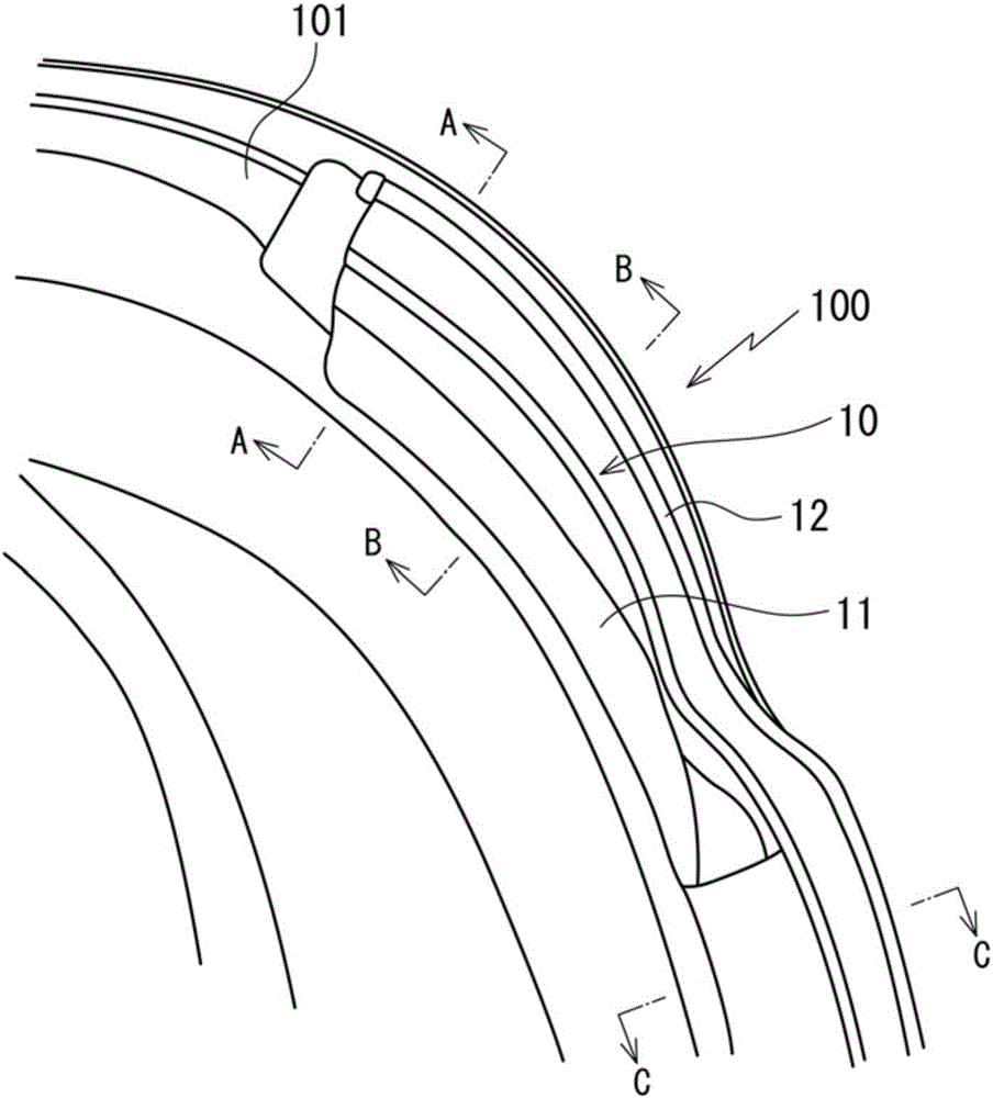
[0065] Next, the end structure of the weather strip according to the embodiment of the present invention will be described with reference to the drawings.

[0066] The end structure of the sealing strip of the embodiment of the present invention, such as figure 1 , Figure 9 , Figure 10 As shown, the slide door 100 that moves forward and backward along the body of a station wagon, a van, or a sedan is attached to a section L where the flange 101 cannot be set.

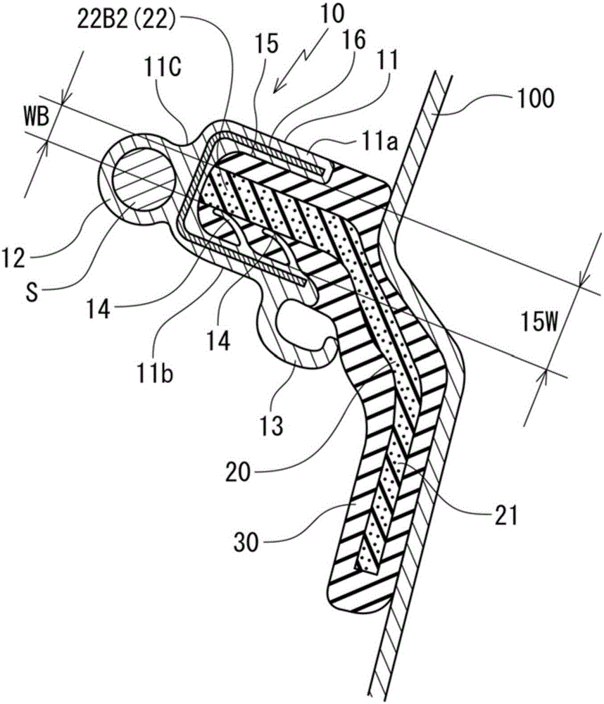
[0067] like Figure 2 to Figure 4 As shown, the weather strip 10 is formed by integrally forming a hollow portion 12 on an installation base 11 having a substantially U-shaped cross section, and an insert 20 is embedded therein. In addition, the hollow portion 12 is a hollow portion extending in the up-down direction for later inserting a sensor (pressure-sensitive sensor) S for when the sliding door 100 is sandwiched between the door opening. When a foreign object such as a part of the human body (finger or hand ...


PUM


Abstract

A structure of an end part of a weather strip is for use on a space in which a flange breaks off. The flange is on a door of an automobile. The weather strip is formed by integrally molding a hollow part with an installation base member having a U-shaped cross section. The weather strip has an insert buried therein. The insert has a convex formed thereon. The convex extends in a longitudinal direction of the weather strip. A concave of the installation base member on the end part of the weather strip formed by extrusion molding is fit on the convex, and die molding material integrally connects the end part of the weather strip formed by extrusion molding and the insert.

Description

technical field [0001] The present invention relates to an end structure of a weather strip installed in an area where a flange cannot be set, such as the upper portion or the lower portion of a sliding door that moves forward and backward along a vehicle body such as a station wagon, a van, or a sedan, and The molding method of the end of the weather strip. Background technique [0002] For example, in the case of fixing the weather strip to a flange formed on an automobile door or a body on the side of the door opening, it is generally known to use a claw shape provided inside a mounting base having a substantially U-shaped cross section. The method of fixing the reaction force of the part. [0003] However, in such Figure 10 In the case of the vehicle body as shown, based on reasons such as the small corner R and the large door opening, as Figure 9 As shown, like the upper part X or the lower part Y of the sliding door 100 , there may be a section L where the flange 1...

Claims


Application Information

Patent Timeline
Patent Type & Authority Applications(China)
IPC IPC(8): B60J10/84B60J10/86B60J10/36B60Q9/00
CPCB60Q9/00E05F15/48E05Y2900/531B60J10/18B60J10/22B60J10/86B60J10/21B60J10/80
Inventor 川口敏路松本美智彦
Owner NISHIKAWA RUBBER
Why Eureka
Try Eureka