Mould flat steel continuous reversible rolling machine unit and mould flat steel rolling method
A technology for rolling mills and flat steel, which is applied in the field of continuous reversible rolling mills for die flat steel and die flat steel rolling. It can solve the problems of specification restrictions, large energy consumption, and low dimensional accuracy, and achieve increased size and scope. , reduce energy consumption, and meet the effect of product quality accuracy
- Summary
- Abstract
- Description
- Claims
- Application Information
AI Technical Summary
Problems solved by technology
Method used
Image
Examples
Embodiment 1
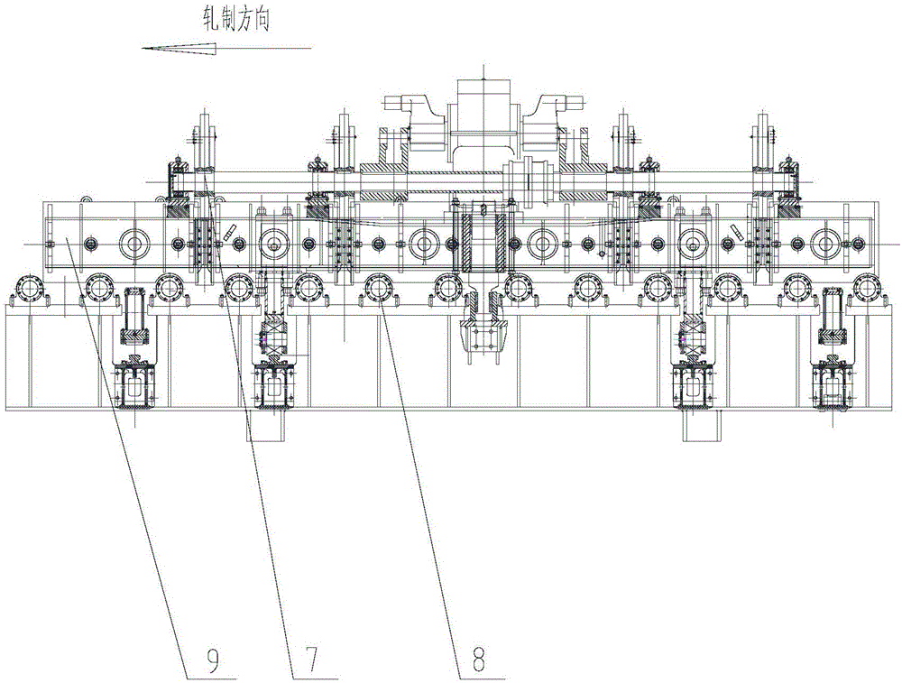
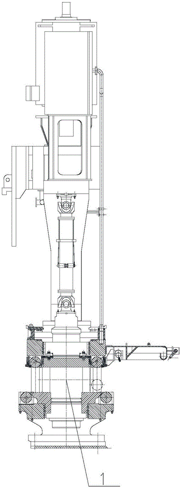
[0096] Example 1, such as figure 1 , Figure 3 to Figure 6 , Figure 8 with Figure 9As shown, a continuous reversible rolling mill for die flat steel comprises vertical rolling mill and horizontal rolling mill; described vertical rolling mill comprises vertical rolling mill I1 and vertical rolling mill II3; described horizontal rolling mill comprises horizontal rolling mill I2 and horizontal rolling mill Rolling mill II4; the vertical rolling mill I1, the horizontal rolling mill I2, the vertical rolling mill II3 and the horizontal rolling mill II4 are arranged in sequence according to the rolling direction on the horizontal working surface; the vertical rolling mill I1, the horizontal rolling mill I2, the vertical rolling mill The adjacent rolling mills of the rolling mill II3 and the horizontal rolling mill II4 are connected and fixed by connecting frames.
[0097] Both sides of the horizontal rolling mill I2 and the horizontal rolling mill II4 are respectively provided ...
Embodiment 2
[0100] Example 2, such as figure 1 , Figure 3 to Figure 6 , Figure 8 and Figure 9 As shown, a die flat steel rolling method using the continuous reversible rolling mill for die flat steel of Embodiment 1, setting vertical rolling mill I1, horizontal rolling mill I2, vertical rolling mill II3 and horizontal rolling mill II4 as E1, F1 respectively , E2 and F2.
[0101] - The first rolling pass: rolling through E1, F1, E2 and F2 in sequence, the specific steps are as follows:
[0102] S1. First distribute the reductions of E1, F1, E2 and F2 four-stand rolling mills according to regulations, and then use a certain load distribution calculation method to determine E1, F1, E2 and F2 The thickness of the outlet plate of each rack;
[0103] S2. Calculation and verification of bite angle;
[0104] S3. Determine the entrance speed of the F2 frame according to regulations and table look-up methods;
[0105] S4, with the F2 frame as the benchmark, use the flow constant law to c...
Embodiment 3
[0127] Example 3, such as Figure 1 to Figure 9 As shown, a continuous reversible rolling mill for die flat steel comprises vertical rolling mill and horizontal rolling mill; described vertical rolling mill comprises vertical rolling mill I1 and vertical rolling mill II3; described horizontal rolling mill comprises horizontal rolling mill I2 and horizontal rolling mill Rolling mill II4; the vertical rolling mill I1, the horizontal rolling mill I2, the vertical rolling mill II3 and the horizontal rolling mill II4 are arranged in sequence according to the rolling direction on the horizontal working surface; the vertical rolling mill I1, the horizontal rolling mill I2, the vertical rolling mill The adjacent rolling mills of the rolling mill II3 and the horizontal rolling mill II4 are connected and fixed by connecting frames.
[0128] Both sides of the horizontal rolling mill I2 and the horizontal rolling mill II4 are respectively provided with a group of guide mechanisms; the gui...
PUM
| Property | Measurement | Unit |
|---|---|---|
| thickness | aaaaa | aaaaa |
| thickness | aaaaa | aaaaa |
| thickness | aaaaa | aaaaa |
Abstract
Description
Claims
Application Information
 - R&D Engineer
- R&D Manager
- IP Professional
- Industry Leading Data Capabilities
- Powerful AI technology
- Patent DNA Extraction
Browse by: Latest US Patents, China's latest patents, Technical Efficacy Thesaurus, Application Domain, Technology Topic, Popular Technical Reports.
© 2024 PatSnap. All rights reserved.Legal|Privacy policy|Modern Slavery Act Transparency Statement|Sitemap|About US| Contact US: help@patsnap.com


