
A needle clamp kit

The technology of a needle head and a jig is applied in the field of clamping devices, which can solve the problems of scrapping, unable to insert the needle, and increase the offset, and achieve the effects of convenient use, low cost and simple structure

Active Publication Date: 2019-03-05
CHENGDU JIESHIDE SCIENCE AND TECHNOLOGY CO LTD
View PDF13 Cites 0 Cited by
  • Summary
  • Abstract
  • Description
  • Claims
  • Application Information

AI Technical Summary

Problems solved by technology

[0004] The purpose of the present invention is to overcome the existing self-adaptive chuck clamped on the side wall of the needle column in the prior art, although the needle can be easily installed in the clamp or disassembled from the clamp; however, the self-adaptive The two clips of the chuck are in point contact with the needle, and there is a gap between the needle and the fixture. The needle can rotate around the contact point between the two clips and the needle relative to the fixture. When the dispensing robot repeatedly inserts the needle into the medicine bottle or After the infusion bag, the offset of the needle relative to the needle insertion port of the medicine bottle or the infusion bag increases, resulting in the inability to insert the needle in the future, and the mechanical movement may also cause forced extrusion between the needle and the medicine bottle or the infusion bag, making it scrapped To solve the above shortcomings, a needle clamp kit is provided

Method used


Image

  • A needle clamp kit
  • A needle clamp kit
  • A needle clamp kit

Examples


Embodiment

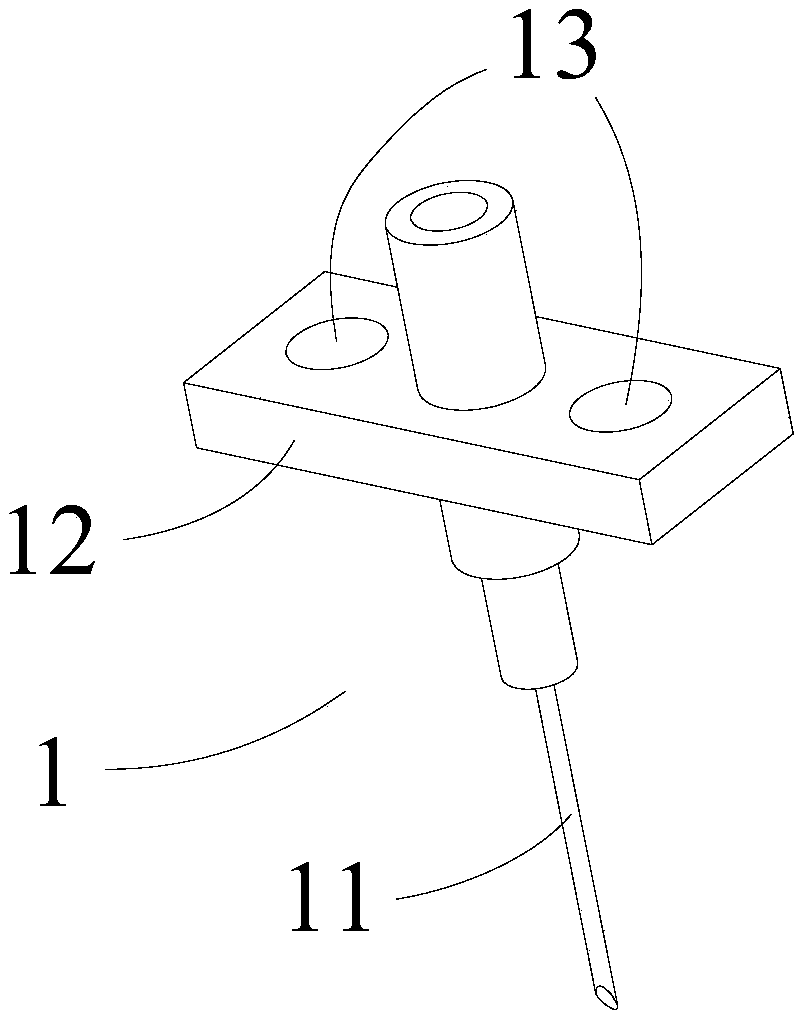
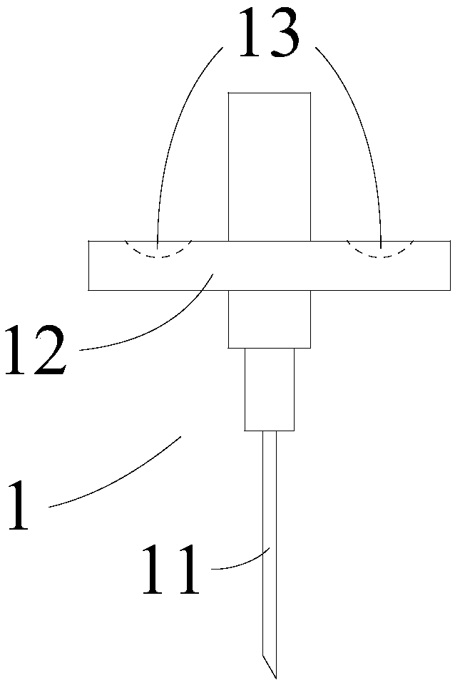
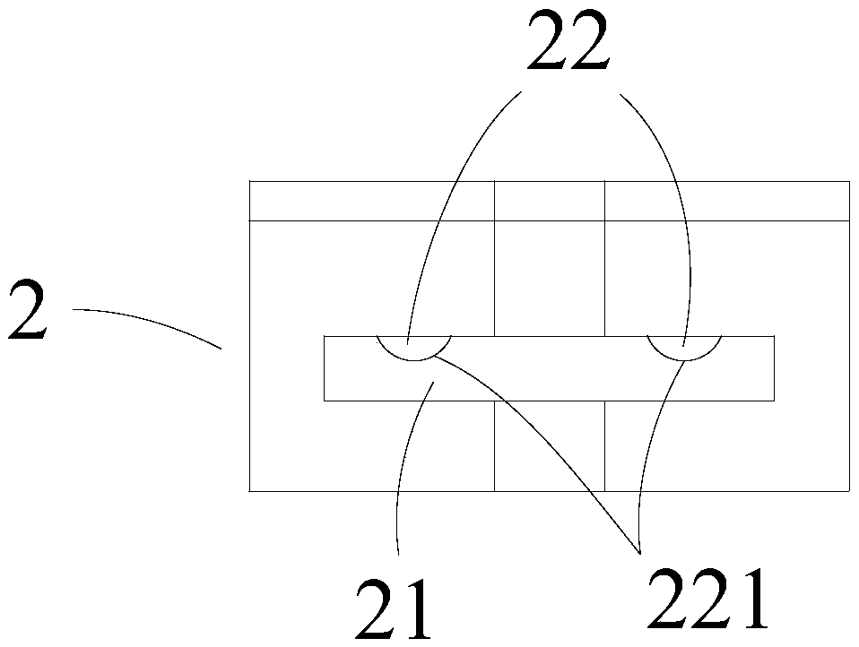
[0034] like Figure 1-5 As shown in the present invention, a needle 11 fixture set includes a clamping plate 1 and a clamping head 2 .

[0035] like figure 1 and 2 As shown, the clamping plate 1 includes a positioning piece 12 connected to the needle head 11, and the positioning piece 12 is provided with two spherical grooves 13, such as image 3 and 4 As shown, the chuck 2 includes a box body 23, and the box body 23 is provided with a locking groove 21 and at least one elastic lock head 22, and all the elastic lock heads 22 are arranged in the box body 23, each Each of the elastic lock heads 22 includes a spherical end 221, and the spherical end 221 can freely expand and contract in the engaging groove 21, and the engaging groove 21 is adapted to the positioning piece 12, and each of the spherical surfaces The end portion 221 is adapted to the spherical groove 13 .

[0036] Wherein, the needle head 11 and the positioning piece 12 are integrally formed to form the clampin...


PUM


Abstract

The invention discloses a needle head and fixture suite. The needle head and fixture suite comprises a clamping connection plate and a clamping head; the clamping connection plate comprises a positioning slice connected with a needle head; the positioning slice is provided with sphere grooves; the clamping head comprises a clamping connection groove and elastic locking heads; each elastic locking head is arranged in the clamping head and comprises a sphere end, and the sphere ends extend into the clamping connection groove; the clamping connection groove is matched with the positioning slice; and the sphere ends are matched with the sphere grooves. By applying the fixture, when the clamping connection plate is clamped into the clamping connection groove, the positioning slice jacks the elastic locking heads to be compressed; when the sphere ends enter the sphere grooves, the needle head is fixed by the clamping head, and meanwhile the elastic locking heads abut against the sphere grooves; the gap between the positioning slice and one side of the clamping connection groove is eliminated, so that the positioning slice is tightly attached to the clamping connection groove and is in face contact with the clamping connection groove; and meanwhile, the positioning slice is fixedly connected with the needle head, namely, the freedom degree of the needle head is limited, and the effect that the needle head cannot rotate is ensured. The clamping head is simple in structure, using is convenient, the cost is low, and the effect is remarkable.

Description

technical field [0001] The invention relates to a clamping device, in particular to a needle clamp set. Background technique [0002] The existing dispensing robot that uses the needle suction method to dispense medicine is equipped with a clamp that holds the needle, and part of it uses an adaptive chuck that uses elastic clamping parts to hold the needle. Compared with the mechanical gripper, since it does not need to The opening and closing parts with complex structure and electric drive save cost and energy, facilitate the installation and removal of needles, and are widely used. [0003] The existing self-adaptive collet is clamped on the cylindrical side wall of the needle, although the needle can be easily installed in the fixture or disassembled from the fixture; however, the two clips of the self-adaptive collet are in point contact with the needle, In addition, there is a gap between the needle head and the fixture, and the needle head can rotate around the contac...

Claims


Application Information

Patent Timeline
Patent Type & Authority Patents(China)
IPC IPC(8): A61J1/20
CPCA61J1/20
Inventor 郑永强柏轲
Owner CHENGDU JIESHIDE SCIENCE AND TECHNOLOGY CO LTD
Learn More