Rotatable endoscope apparatus
A rotating and endoscopic technology, which is applied in the fields of endoscopy, medical science, surgery, etc., can solve the problem of many holes in the connection part, and achieve the effect of easy maintenance, good safety and reliability, and improved operating comfort
- Summary
- Abstract
- Description
- Claims
- Application Information
AI Technical Summary
Problems solved by technology
Method used
Image
Examples
Embodiment 1
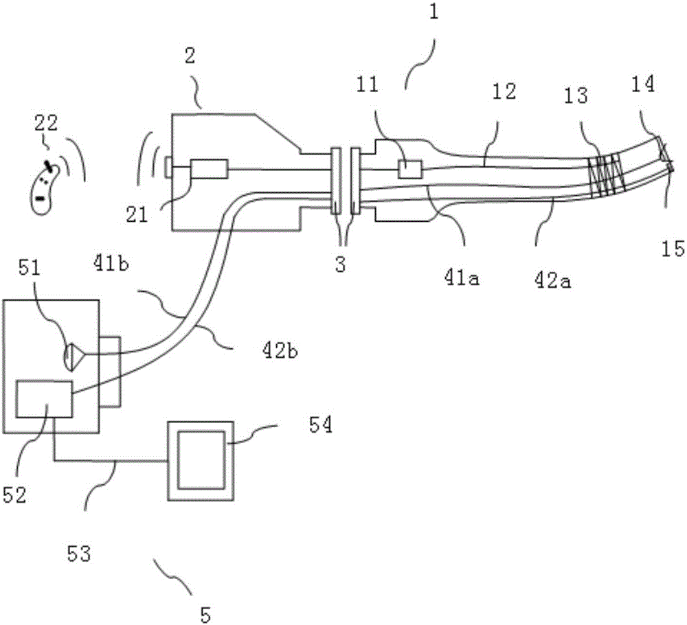
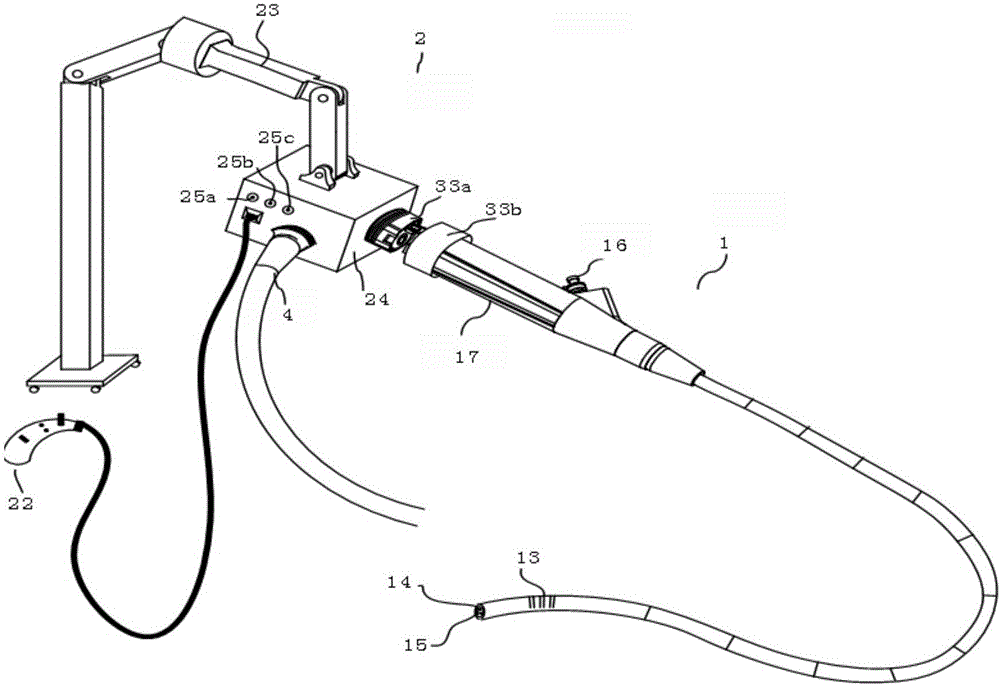
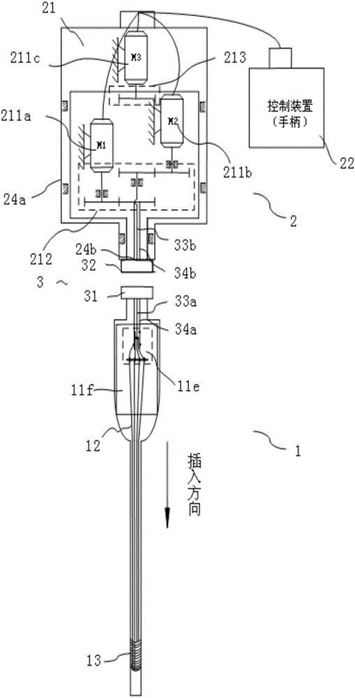
[0050] The first embodiment of the present invention is a double thread method of nut screw type, refer to Figure 1 to Figure 10 Be explained. The purpose of this embodiment is to respectively realize the reciprocating motion of the pulling wire group 12 (specifically, the reciprocating motion of the pulling wires 12a and 12b and the pulling wires 12c and 12d) through the rotation of the first rotating shaft 33a and the second rotating shaft 34a. ).
[0051] like figure 1As shown, the rotating endoscope device provided by this embodiment is composed of two parts, the insertion part 1 and the operation part 2. The shaft rotates the connection mechanism 3 to realize the detachable connection. The insertion part 1 mainly includes a bending unit composed of a driving steering unit 11 , a drawing wire group 12 and a snake bone unit 13 , as well as an illumination unit 14 and an imaging unit 15 . The bending unit has at least two bending directions. The operating part 2 includ...
Embodiment 2
[0067] Figure 16a and Figure 16b Example 2 will be described. This embodiment mainly transforms the drive steering unit 11 into a drive differential shaft type belonging to the category of double threads. The second rotating shaft 34a is connected by a lateral transmission (gears, belts, sprockets). Other than that, the basic structures of the operation part and the insertion part of this embodiment are basically the same as those of the first embodiment. The purpose of this embodiment is to respectively realize the reciprocating motion of the pulling wire group 12 (specifically, the reciprocating motion of the pulling wires 12a and 12b and the pulling wires 12c and 12d) through the rotation of the first rotating shaft 33a and the second rotating shaft 34a. ).
[0068] like Figure 16a and Figure 16b As shown, the other end of the first rotating shaft 33a is fixed with a first nut unit 11a and a second nut unit 11b, and the second rotating shaft 34a meshes with a spur...
Embodiment 3
[0070] Figure 17 Example 3 will be described. This embodiment mainly transforms the drive steering unit 11 into a drive coaxial type under the category of single thread. The first rotating shaft 33a and the second rotating shaft 34a change the direction of the pulling wire through a phase changing unit (gear, pulley, belt, sprocket). Other than that, the basic structures of the operation part and the insertion part of this embodiment are basically the same as those of the first embodiment. The purpose of this embodiment is to respectively realize the reciprocating motion of the pulling wire group 12 (specifically, the reciprocating motion of the pulling wires 12a and 12b and the pulling wires 12c and 12d) through the rotation of the first rotating shaft 33a and the second rotating shaft 34a. ).
[0071] like Figure 17 As shown, the other end of the first rotating shaft 33a is fixed with the first nut unit 11a, and the end of the second rotating shaft 34a is fixed with th...
PUM
 Abstract
Description
Claims
Application Information
 - R&D Engineer
- R&D Manager
- IP Professional
- Industry Leading Data Capabilities
- Powerful AI technology
- Patent DNA Extraction
Browse by: Latest US Patents, China's latest patents, Technical Efficacy Thesaurus, Application Domain, Technology Topic, Popular Technical Reports.
© 2024 PatSnap. All rights reserved.Legal|Privacy policy|Modern Slavery Act Transparency Statement|Sitemap|About US| Contact US: help@patsnap.com


