Control the maximum allowable speed of the UAV handling system
A maximum speed, maximum allowable technology, applied in the direction of joint control, speed/acceleration control without auxiliary power, etc., can solve the problem that the UAV cannot control the maximum allowable flight speed automatically.
Active Publication Date: 2011-04-27
CHENGDU AIRCRAFT INDUSTRY GROUP
View PDF0 Cites 3 Cited by
- Summary
- Abstract
- Description
- Claims
- Application Information
AI Technical Summary
Problems solved by technology
The object of the present invention is for prior art unmanned aerial vehicle self can not self-control maximum allowable flight speed range
Method used
View moreImage
Smart ImageViewing Examples


Examples
Embodiment Construction
[0045] f) Exit the program.
[0055] 4. exit the program.
[0061] 9. exit the program.
[0066] Exit the program.
[0072] d) Exit the program.
Login to View More PUM
 Abstract
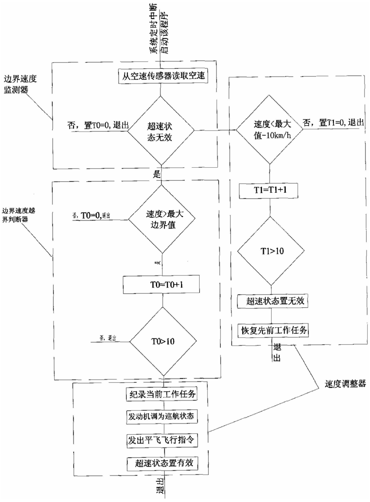
The invention relates to a disposal system for controlling the maximum allowable speed of an unmanned aerial vehicle, comprising: a control computer, a speed sensor, a rudder surface control system, a throttle control system and / or a parachute system connected through the computer. Among them, it is equipped with a control computer that provides a timing interruption not greater than 120ms, and is equipped with a maximum speed fault handling program component that judges whether it is necessary to control the aircraft speed according to the speed provided by the airspeed sensor. The program component is composed of a speed over-limit control module for controlling computer timing interruption start and a maximum speed fault handling control module. On the one hand, the invention limits the flight of the aircraft within the maximum allowable flight speed range; on the other hand, when the aircraft speed exceeds the maximum speed and fails to be controlled, the aircraft pitch angle is controlled by the program components so that the aircraft is always within the allowable speed range Fly, or control the plane to return home or open the parachute in time to avoid flight accidents caused by the speeding of the plane.
Description
Technical field of control UAV maximum allowable speed disposal system [0001] The present invention relates to a handling system for controlling the flight speed of an unmanned aerial vehicle. Background technique Unmanned aerial vehicle, is a kind of by radio remote control equipment or by its own program control device manipulation, beyond visual distance execution pair Unmanned aircraft for air combat missions. Unlike manned aircraft, drones have the space to load and the capacity to control computers. The amount and calculation speed are limited, the flight control system is simple, the sensors carried by itself are few, the flight control ability is weak, and failures occur It cannot be ruled out in itself, and crash accidents are prone to occur. It requires the ground control center to monitor the flight parameters of the aircraft To control and make instantaneous adjustments, rely to a large extent on the various sensors of the machine to obtain information. ...
Claims
Login to View More Application Information
Patent Timeline
 IPC IPC(8): G05D13/28B64C19/02
Inventor 李涛宋承志夏斌
Owner CHENGDU AIRCRAFT INDUSTRY GROUP
Features
- R&D
- Intellectual Property
- Life Sciences
- Materials
- Tech Scout
- Unparalleled Data Quality
- Higher Quality Content
- 60% Fewer Hallucinations
Learn More Browse by: Latest US Patents, China's latest patents, Technical Efficacy Thesaurus, Application Domain, Technology Topic, Popular Technical Reports.
© 2025 PatSnap. All rights reserved.Legal|Privacy policy|Modern Slavery Act Transparency Statement|Sitemap|About US| Contact US: help@patsnap.com