light fighter wing

A technology for fighter jets and wings, applied in the direction of wings, fuselage, aircraft parts, etc., to achieve the effect of meeting the strength, meeting the use and maintenance requirements, and simple installation and disassembly

Active Publication Date: 2010-08-04
CHENGDU AIRCRAFT INDUSTRY GROUP
View PDF0 Cites 13 Cited by
  • Summary
  • Abstract
  • Description
  • Claims
  • Application Information

AI Technical Summary

Problems solved by technology

En

Method used


Image

  • light fighter wing
  • light fighter wing
  • light fighter wing

Examples


Embodiment Construction

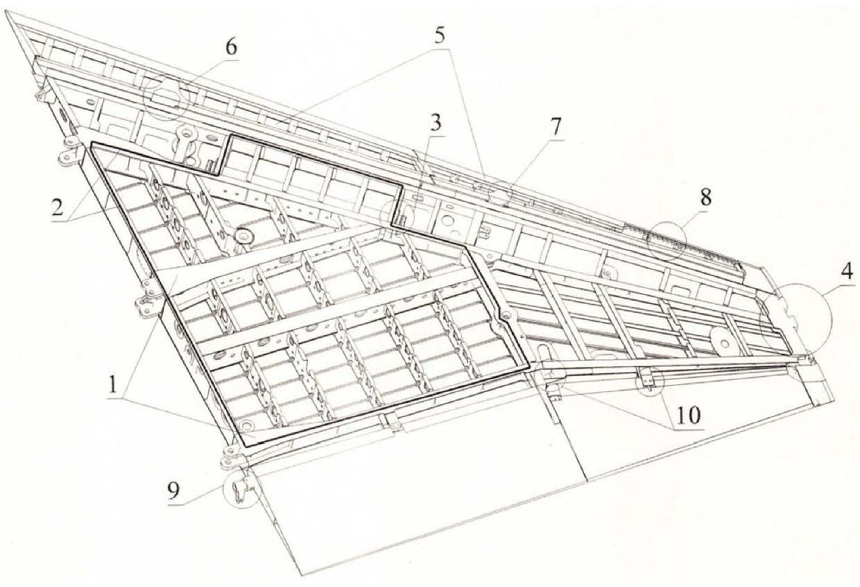
[0024] The swivel bearing material of the front skirt is made of stainless steel. Since the main girder and the rear girder are soaked in fuel oil, the main bearing girder 1 can

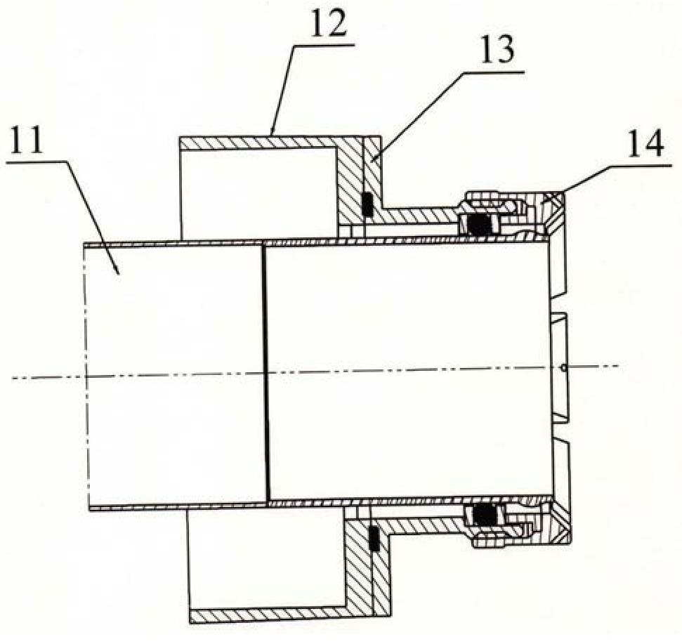
[0028] Fig. 3 has described the wing hanging wingtip projectile structure 4 shown in Fig. 1. Wingtip projectile structure design, in domestic light fighter design

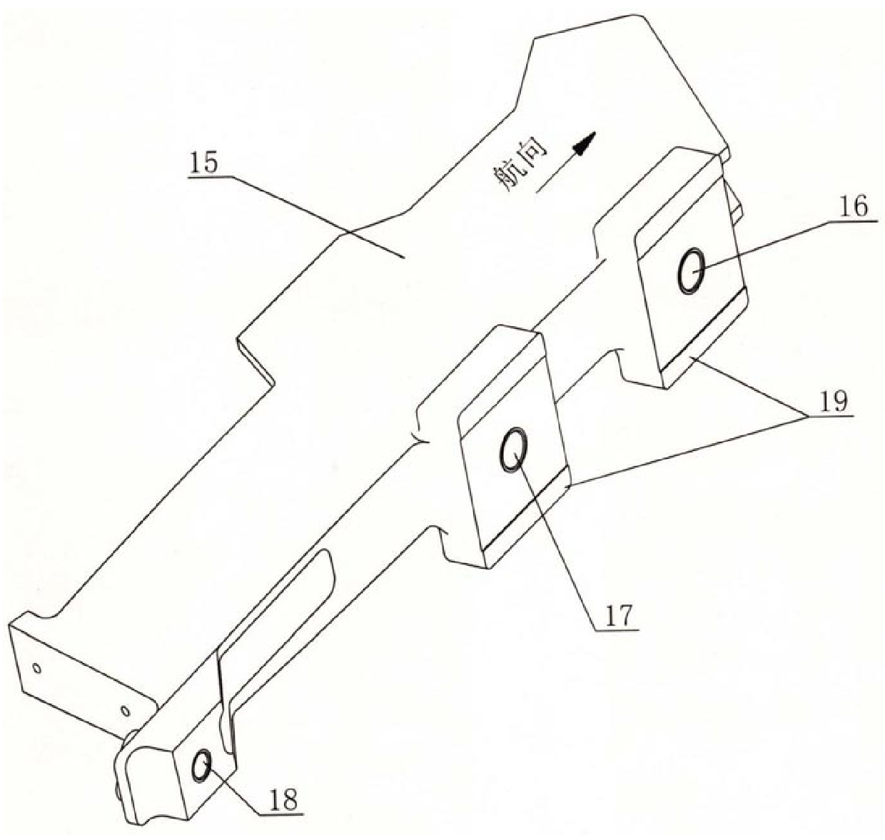
[0029] The trailing edge flap root joint 9 shown in FIG. 1 is depicted in FIG. 4 . The trailing edge flap passes through the root, middle, and tip three

[0031] The aileron root joint is connected with the seventh rib arm of the wing and the control rod. The root joint acts both as a turning rocker arm and


PUM


Abstract

The invention provides a light fighter wing. The leading edge flap of the present invention is a full-span motorized front flap, the outer section of the front flap is slender, and the airfoil is relatively thin. The frame around the rear beam and the integral fuel tank and its integral fuel tank are sealed without grooves. Between the front ribs of the leading edge of the wing, there is a dry duct for the flight control rod passing through the integral fuel tank area along the span direction. The present invention is the first in China to have no grooves, no oil separators, the main bearing beam and the integral oil tank without grooves and seals, which reduces the structural weight of the wings. The embedded structure of the sealing edge between the leading edge flap and the main wing surface ensures that the sealing edge will not be torn when the aircraft is flying. The invention successfully solves the first use of the wingtip projectile external hanging structure technology in domestic light fighters. The invention also provides the application of stainless steel forgings which have never been used in domestic aircraft on the wing main girder and rear girder. It solves the technical bias that the length-to-diameter ratio of the dry conduit is large along the span, which is difficult to solve.

Description

Technical Field of Light Fighter Wing The present invention relates to a kind of wing of warplane, especially the wing of multipurpose light fighter. technical background The fighter wing is the main lifting surface of the aircraft, which bears most of the aerodynamic loads of the aircraft, and is to form the whole aircraft and the parameters A key component for aerial combat. The wing is a middle single wing, which is divided into left and right wings, and is an all-metal structure, and its plane shape is trapezoidal. The wing is made up of main airfoil, leading edge flap, trailing edge flap, aileron, wing knife and fairing foreskin. Due to the immersion of the main beam and rear beam of the wing Because of being soaked in fuel, at present, the framework and partitions around the overall fuel tank of aircraft wings at home and abroad usually use grooves to seal envelope design. Moreover, the front beam, main beam, and rear beam of the main load-bearing frame around...

Claims


Application Information

Patent Timeline
IPC IPC(8): B64C3/18B64C1/22B64C3/28
Inventor 张世全帅朝林陈家林戴干常陈良刘晓明邱明镝彭兴国何秋蓉徐炎胡伯仁
Owner CHENGDU AIRCRAFT INDUSTRY GROUP
Why Eureka
Try Eureka