
LED display control method, image splicing edge optimization method and processing device

An image splicing and edge technology, applied in image communication, TV, color TV components, etc., can solve the problems of poor display experience, affecting the overall effect, and no edge optimization function, etc., to solve color distortion and improve image quality Effect

Active Publication Date: 2019-12-24
XIAN NOVASTAR TECH
View PDF8 Cites 0 Cited by
  • Summary
  • Abstract
  • Description
  • Claims
  • Application Information

AI Technical Summary

Problems solved by technology

[0004] However, ordinary video splicers or video processors do not have the edge optimization function when splicing images. In some scenarios, the display effect at the edge of the splicing will be reduced, thereby affecting the overall effect and making the display experience worse.

Method used


Image

  • LED display control method, image splicing edge optimization method and processing device
  • LED display control method, image splicing edge optimization method and processing device
  • LED display control method, image splicing edge optimization method and processing device

Examples


Embodiment Construction

[0024] In order to make the above objects, features and advantages of the present invention more comprehensible, specific implementations of the present invention will be described in detail below in conjunction with the accompanying drawings.

[0025] The following embodiments of the present invention provide a technical solution that can realize image splicing edge optimization. This technical solution can solve the problem of local display distortion caused by image chromatic aberration at the edge of splicing in a video splicer or video processor, thereby improving Stitching effect, improve stitching quality.

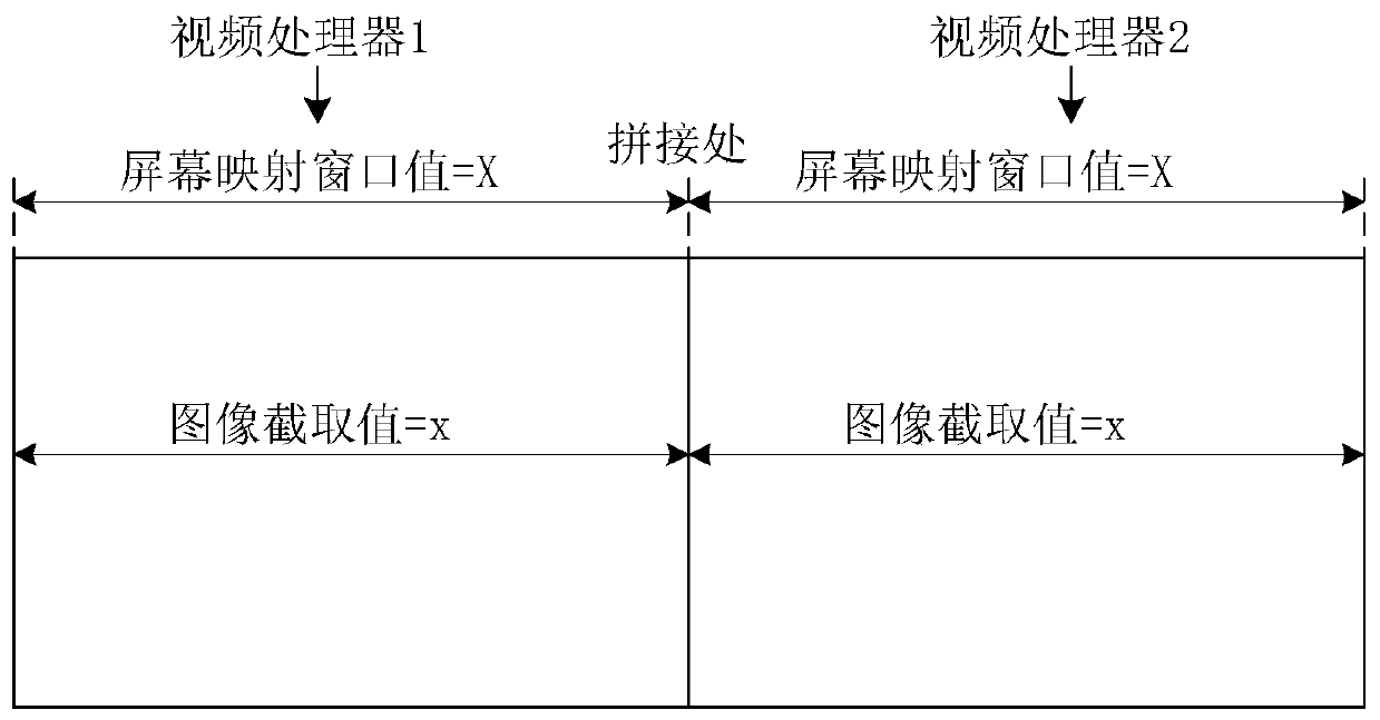
[0026] Specifically, this technical solution adopts the "boundary extension" method, and uses the screen mapping window and image capture to expand the original image boundary, so that the video processing chip in the video processor or video splicer, such as the STDP8028 series chip, can collect its own actual image. The image information on the other side of the s...


PUM


Abstract

The invention provides an LED display control method, an image splicing edge optimization method and an image splicing processing device. Specifically, through adoption of a boundary extension mode, boundary extension is carried out an image interception range, so image data intercepted from input image data comprises the image data of the other side of the imaging splicing edge; the corresponding boundary extension is carried out on a screen mapping window, so the scaling of an image is kept unchanged; and through combination of an original image optimization algorithm of a video processing chip, integrated image optimization is carried out on the intercepted image data. In this way, the video processing chip can optimize the image data out of own display screen load area, thereby solving the color distortion condition of the splicing edge and improving the quality of the image of which splicing edge is processed.

Description

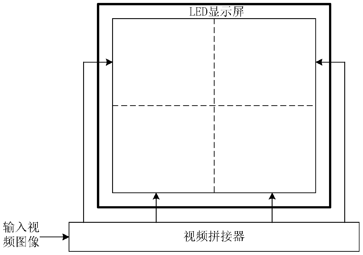
technical field [0001] The present invention relates to the technical field of display control, in particular to an LED display control method, an image splicing edge optimization method, and an image splicing processing device. Background technique [0002] In the field of large-resolution LED display display control, since the number of pixels on the display screen exceeds the loading capacity of a single sending card, the video splicer or the image splicing function of the video processor is often used to complete the display. If the image signal at the splicing edge itself has a large color difference or the color transition is too large, sometimes the visual color distortion will appear at the splicing edge. [0003] figure 1 It is a schematic diagram of an LED display control system architecture using a video splicer in the prior art. Among them, the LED display screen is divided into four display areas, and the video splicer performs an image segmentation operation ...

Claims


Application Information

Patent Timeline
Patent Type & Authority Patents(China)
IPC IPC(8): H04N5/262
CPCH04N5/262H04N5/2628
Inventor 周晶晶庞刚宗靖国
Owner XIAN NOVASTAR TECH
Learn More